STRUCTURE OF A SUB-MODULE
The Sub-Modules are assemblies that connect together to form Macro-Modules, and these Macro-Modules then connect to each other to form application structures. These Sub-Modules are all identical to each other in all aspects of structure (e.g., mechanically, electronically, operationally). They consist of two different types of bases and a leg. One of the bases is a Core Base Assembly (the “core” being the “nucleus” of the Macro-Module) and the other is the Connecting Plate Assembly. The Core Base Assembly is linked to the Connecting Plate Assembly by a Leg Assembly that can extend and retract. The Core Base Assembly can pivot the Leg Assembly about both axes which are perpendicular to the axis of the Leg Assembly (i.e., it can pivot in any direction just as an arm can pivot being mounted on the shoulder). The Connecting Plate Assembly can rotate in either clockwise or counter-clockwise directions about the axis of the leg. There are two ways the Sub-Modules can connect to each other. One involves the Core Base Assembly; this means of connecting involves connecting each one directly to four others and indirectly to a fifth one to form into a Macro-Module. The other involves the Connecting Plate Assembly; the Macro-Modules connect to each other by using this as a means for connecting together. The Core Base Assemblies can encase a Power Cell that can optionally be present or absent. The Sub-Modules can transmit and receive power and communication signals. If a Macro-Module doesn’t contain a Power Cell then it must utilize adjacent modules to acquire energy.
Figure 8a, below shows 3 views of the Core Base Assembly. It consists geometrically of two rectangular boxes and a square Truncated Pyramid with sides that slope at 45° angles. The rectangular boxes are of the same thickness, but one, shown as the External Block Region in the figure, has a perimeter that is larger than the other, shown as the Internal Block Region in the figure, of a thickness equal to their box thicknesses (the thickness that each rectangular box has in common with each other of being equal in length on those sides). The two rectangular boxes join together such that their centers are aligned and the box thickness perimeter of the larger rectangle circumscribes the smaller rectangle. The pyramid is of a size such that the edges of two opposite sides of the larger end of the pyramid meet flush with the smaller rectangle and have a space on the other two opposite sides that form space on either side of the surface of the smaller rectangle that are also equal in thickness to the box thicknesses of the rectangle shapes. The smaller end of the pyramid is a Connecting Plane for a cube-shaped Power Cell, also shown in the figure. This shape is necessary to allow the Sub-Modules to connect together in a specific pattern. The larger rectangle houses Connecting Points, which consist of pins and holes that are used to bond the Core Base Assemblies together. The Inward Side view is a view of the side that goes into the core of the Macro-Module.
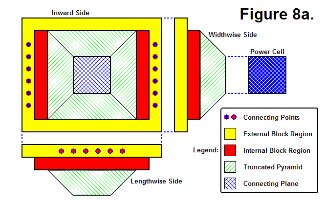
Figure 8b, shown below, also shows 3 views of the Core Base Assembly, except that one of them is an Outward Side view. The Core Base Assembly actually consists of 2 moving parts, an Outer Sub-Module Assembly and an Inner Sub-Module Assembly. This Inner Sub-Module Assembly houses actuators and acts as a universal joint between the Outer Sub-Module Assembly and Leg Assembly that gives it the ability to pivot about both axes. The Perimeter of the Inner Sub-Module Assembly is shown within the Outward Side view of the Core Base Assembly shaded in blue; the rest of the view and the other side views show the region of the Outer Sub-Module Assembly. The Pyramid Well is the region that can be seen behind the Inner Sub-Module Assembly in the Outward Side view, which is a view of the inside of the Truncated Pyramid.
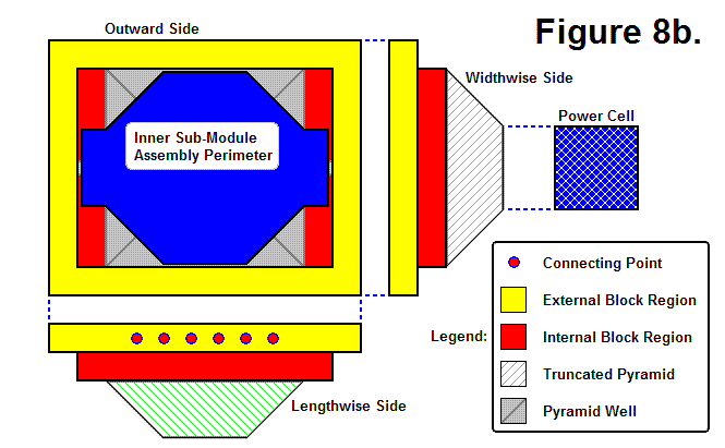
Figure 8c, shown below, shows 4 Core Base Assemblies and a Power Cell aligned to geometrically join together. 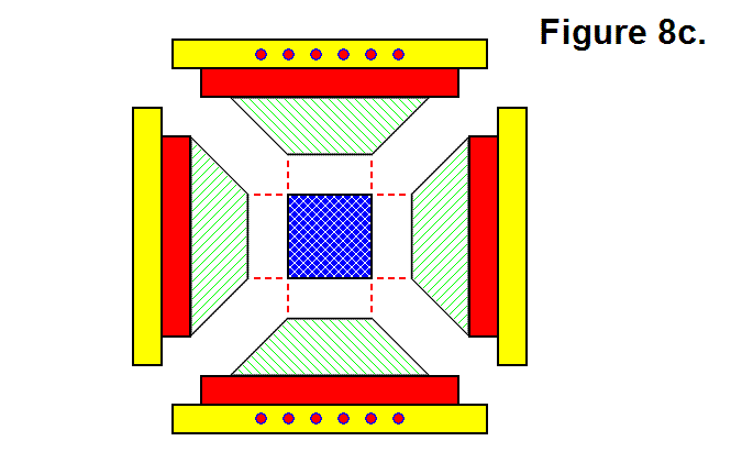
Figure 8d, shown below, shows the 4 Core Base Assemblies and Power Cell from Figure 8c geometrically joined together such that the 4 Core Base Assemblies encompass the Power Cell.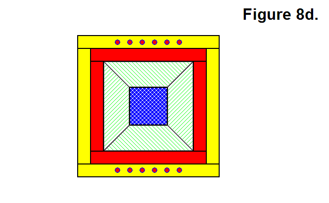
Figure 8e, shown below, shows 5 Core Base Assemblies connected together.
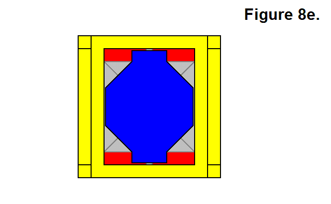
Figure 8f, shown below, shows a 3-dimensional view of 2 Core Base Assemblies geometrically joined together.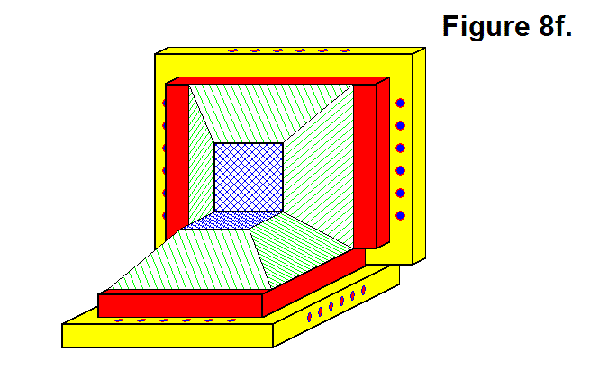
Figure 8g, shown below, shows a 3-dimensional view of 3 Core Base Assemblies connected together. Their geometric pattern, wherein they are sharing a common corner, mechanically bonds them together when the pin-and-hole system is engaged along the edges where another Sub-Module is present.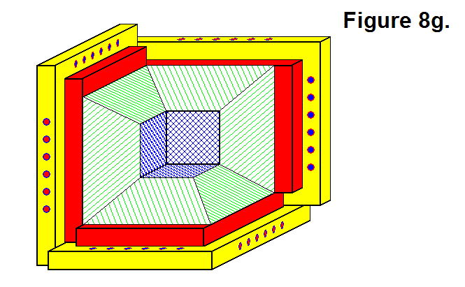
Figure 8h, shown below, shows the Inner Sub-Module Assembly contained within a wireframe outline of a transparent Outer Sub-Module Assembly. The Leg Space & Pivot Channel represents the perimeter of the space within the Inner Sub-Module Assembly in which the Leg Assembly is located and moves.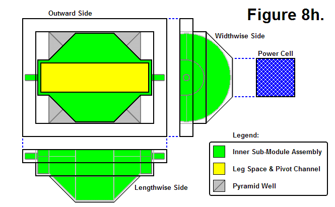
Figure 8i, shown below, shows a hypothetical end of part of the Leg Assembly contained within a wireframe outline of a transparent Inner Sub-Module Assembly. The Leg End Pivoting Range shows the space needed by the end of the Leg Assembly for pivoting.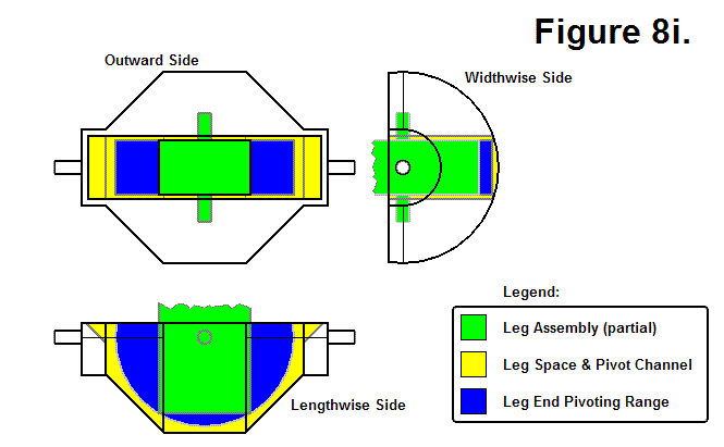
Figure 8j, shown below, shows a hypothetical Leg Assembly of undetermined length. It also shows the Connecting Plate Perimeter in relation to the Leg Assembly; the Connecting Plate and the Leg Assembly have the same center axis of symmetry, and the Connecting Plate can rotate about this axis. The Leg Assembly basically consists of a series of hollow tubes to allow it to extend and retract.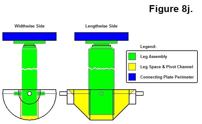
Figure 8k, shown below, shows the Connecting Plate Surface of the Connecting Plate Assembly. The Connecting Plate Arc Cross Section is a “side view” diagram of the Connecting Plate Assembly’s surface. The Connecting Plate Outer Ring serves as the mounting surface for the hooks and houses the plungers. This hook and plunger system acts as an interlocking mechanism between the two plates. The Connecting Plate Center Circle hypothetically serves as a region where electromagnets and communication components are housed.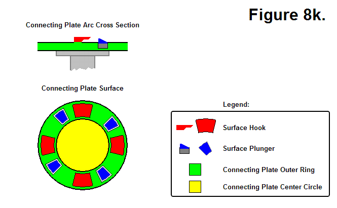
Figure 8m, shown below, shows how two Connecting Plates from different modules can connect together. States 1 through 6 show the Connecting Sequence of the two plates, and states 6 through 9 show the Disconnecting Sequence of the two plates. To connect, the red plate engages the blue plate by rotating to the left, as shown in sequences 1-5; in sequence 6 the plungers are extended out to lock the plates together. To disconnect, the plungers are retracted in, as shown in sequence 7, and the red plate disengages the blue plate by rotating to the right, as shown in sequences 8 and 9.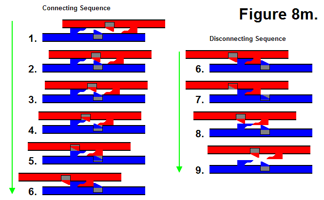
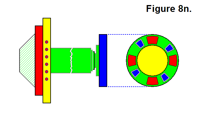
Figure 8n, shown below, shows a full Lengthwise Side view of a Sub-Module along with a Connecting Plate Surface view.