LEG PIVOT RANGE REQUIREMENT
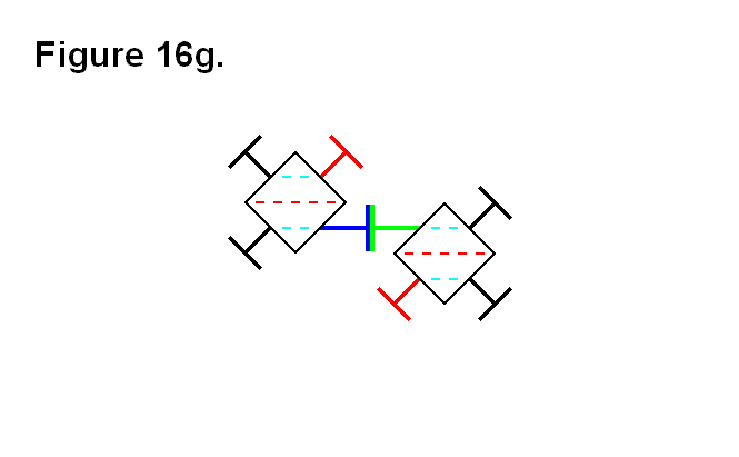
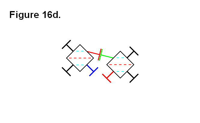
In the following figures, all the dashed lines are parallel to each other. The dashed red lines indicate imaginary lines between the two opposite corners of the cube-shaped nucleus, and the dashed light-blue lines indicate imaginary lines connecting the centers of the face of the cube-shaped nucleus, where the legs connect to them to pivot. Figure 16a shows how two modules connected together with 2 pairs of legs need the flexibility of the legs to be able to pivot at least 45° to the face of the cube-shaped nucleus.
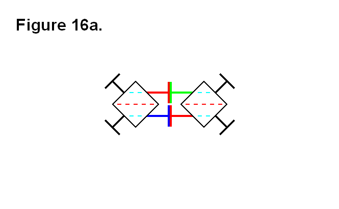
Figure 16b shows a circumstance where the legs need to be able to pivot more than 45° in order for the two cells to connect together; it is the situation where the legs need to be able to pivot the furthest, which is determined by the dashed red lines being aligned with light blue dashed lines. The actual angle value is determined by how close the two cells can be to each other, and how close the two cells can be to each other is determined by the length of the fully retracted telescoping shaft (the leg) plus the thickness of the connecting plate.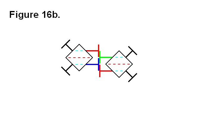
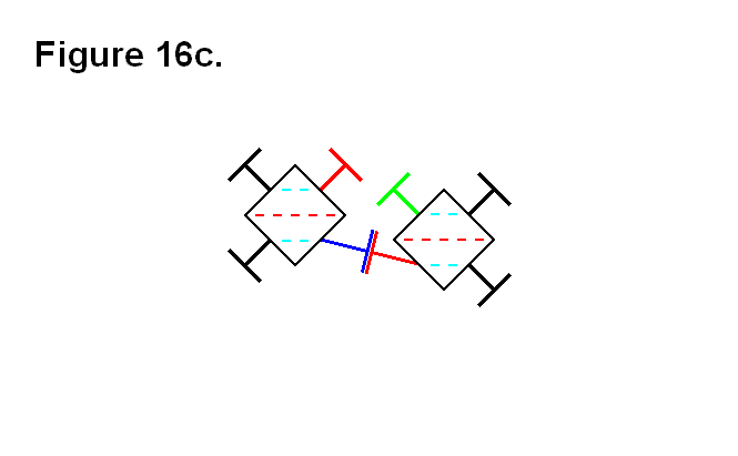
Figures 16c and 16d show one way (they’re both the same type of connection, one is an upside-down view of the other) for the two cells to connect together when they are in the positions of the cells in figure 16b. The closest the two cells can come to each other in this situation is a value that is proportional to the absolute value of the tangent function with the argument value of φ + 45°, where φ is the angle between the face of the cube and the leg that is less than 45°. The ideal leg pivot range angular limit orthogonal to the face of the cube to implement would be as close to around 60° as possible, because as the angle approaches 45° the distance approaches infinity (in an exponential growth-like rate); it is not necessary to go beyond a leg pivot angular limit of about 60°, because anything greater than that is an approximately linearly decreasing rate, and would require the unfeasible implementation of the legs (i.e., they would have to be extremely thin) and other components that would be affected.
 |
 |
Figures 16e shows the two cells from figure 16b connected together using both pairs of legs. This or the connection arrangements of figures 16c and 16d would be the choice for connecting the two cells together if the two red dashed lines from each cell are not going to extend, beyond the boundary indicated by the light-blue dashed line, to be any further apart from each other than this.
In figure 16f, the two cells from figure 16b are connected together in an alternative way to the way the cells are connected together in figures 16c and 16d. This connection arrangement would be the choice for connecting the two cells together if the two red dashed lines from each cell are going to extend, beyond the boundary indicated by the light-blue dashed line, to be any further apart from each other than this.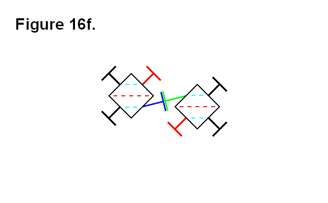
In figure 16g, the two cells are in positions where the two red dashed lines are farther apart, and the legs are back to being pivoted at 45° angles to the faces of the cube-shaped nuclei.