GEOMETRICAL CELL DIMENSION LIMITS AND REQUIREMENTS
In order to be able to achieve some of the needed features and capabilies, there are some minimum requirements in length ratios and pivot angles which can be calculated. There are also certain constraints in length ratios imposed by the geometric shapes of the modules. Figure 12a shows equivalences of module schematics, a basic more symbolic version on the left side, and a more detailed image of a cell on the right side. The image on the right side is the one that will be used as a template for the subject matter of this article. The connecting plates (a side view) are shaded in yellow; the black lines going from the connecting plates to the inner blue square in the center represent the telescoping shafts (the legs). The points where the legs connect to the blue square is where the legs pivot about both axes (in this 2-dimensional image we shall only consider pivoting about the axis that is perpendicular to the plane of the image). The green square represents the perimeter of the cell nucleus, and are also side views of the faces of the cell nucleus. The dashed lines will be used for reference measurements.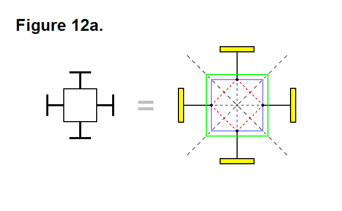
In Figure 12b the distance between points a (the center of the cell) and b (the point that intersects the surface of the connecting plate while the leg is completely retracted, and the leg axis) is equal to A; this line segment is shown as a green line.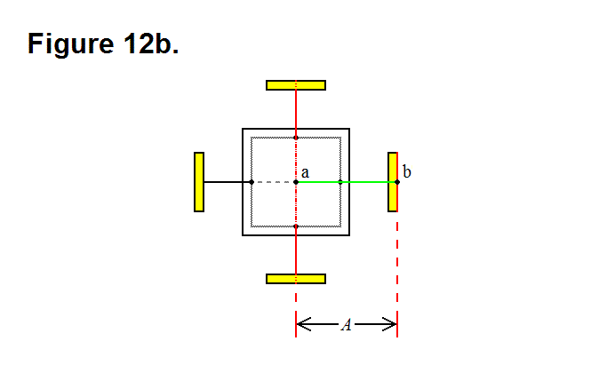
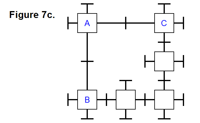
Recalling Figure 7c from the article Diagonal Lattice Reconfiguration Using Leg Extending Capabilities, in order to make it possible for the leg from module A to be able to reach and connect to module C, it is necessary that the legs be able to extend a distance that is long enough to span the distance imposed by the three modules in the bottom row, having module B on the left side, where the row legs that are connected together are fully retracted.
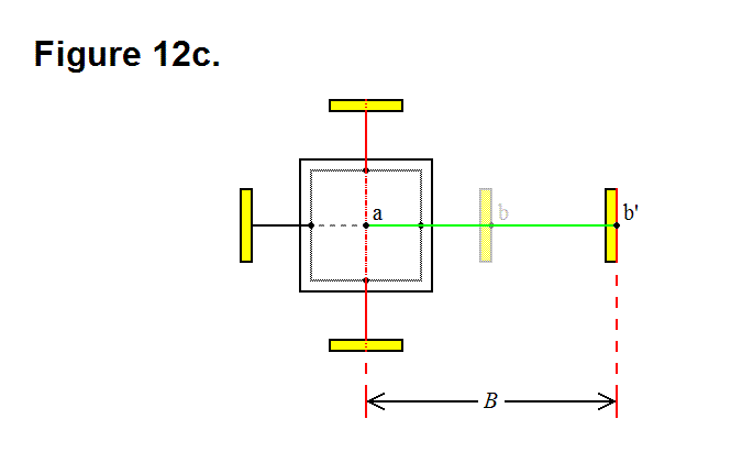
This length of the extended leg associated with this minimum requirement length is represented in Figure 12c as the distance between points a (the center of the cell) and b’ (the point that intersects the surface of the connecting plate while the leg is extended to meet the minimum length requirement, and the leg axis) is equal to B; this line segment is shown as a green line.
An equation can now be formulated; in the top row of Figure 7c, the distance between module A and module C is 2B; in the bottom row (starting with module B) of Figure 7c, the distance between the center of the modules on either end would be 4A. These two values, 2B and 4A, are related in the following way: 2B > 4A; by simlifying this equation the following equation is derived:
B > 2A (Equation 1)
In Figure 12d the leg axis component distance between points c (the corner of the nucleus perimeter) and d (the edge of the underside of the connecting plate while the leg is fully retracted) is equal to C; this corresponds to the distance between the face of the nucleus and the underside of the connecting plate while the leg is fully retracted.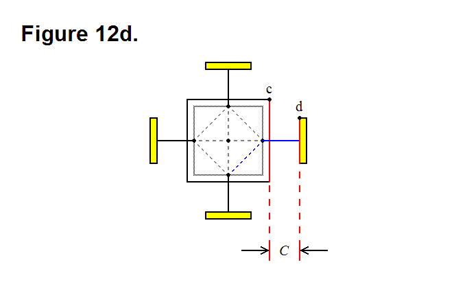
When the leg pivots 45 degrees, as shown in Figure 12e, the connecting plate edge comes close to the corner of the nucleus cube; if length C is not long enough then the connecting plate will strike the nucleus if it attempts to pivot 45 degrees, which will prevent it from being able to achieve this. The red dashed line c’ represents the orthogonal limit plane imposed by the corner of the nucleus, and the red dashed line d’ represents the underside plane of the connecting plate when the leg is fully retracted; these two planes can approach each other, but they cannot be intersecting.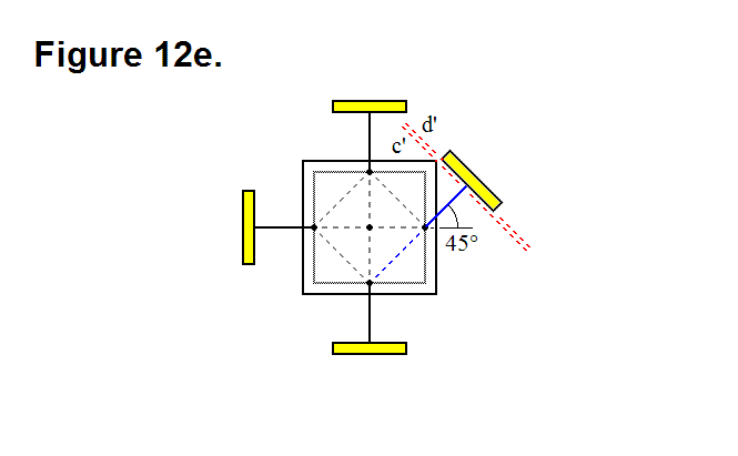
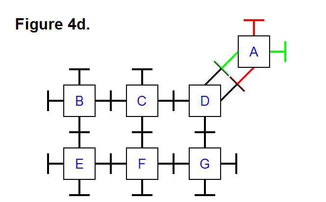
Recalling Figure 4d from the article Basic Module Transfers, Movements, and Connections, in order to make it possible for module A to be able to connect to module D with two adjacent legs from each module, not only it is necessary that the legs be able to pivot by at least 45 degrees, but it is also necessary that the radius of the connecting plates not reach a certain maximum limit
The distance between the center of the two connecting plates on the legs that are pivoted 45 degrees towards each other in Figure 12f is D (it is also equal to the line segment shown as a green line); based on this observation, the circumference of the connecting plate must be less than D, which means that the radius has to be less than D/2.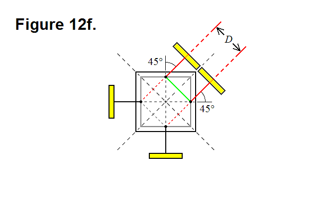
In Figure 12g the distance between points c (the corner of the nucleus) and a’ (the point that intersects the surface of the nucleus and the leg axis) is equal to E; this line segment is shown as a green line.
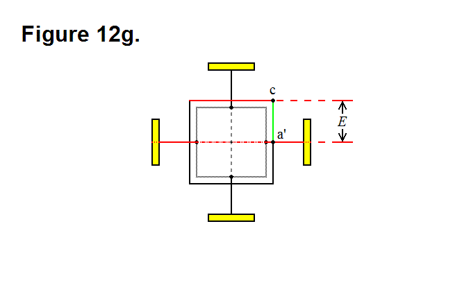
The length between the point where the leg pivots and the face of the nucleus along the axis of the leg is a/2 (see Optimal Ratio Calculation for Module Core Assembly Base Component); by using trigonometry, the following equation can be derived: D = √2(E-a/2). Solving for E produces the following equation:
E = (√2D + a)/2 (Equation 2)
This means that now we know that the radius of the connecting plate has to be less than √2(E-a/2)/2. With some trigonometry and geometric manipulations, and the fact that C has to result in the gap greater than zero between planes c’ and d’ in Figure 12e, the following equation can also be derived: 2C + a > D + √2a. By solving for C in this equation, the following equation can be derived:
C > (D+(√2-1)a)/2 (Equation 3)
If the thickness of the connecting plate along the leg axis is T, then the following equation relating length A to lengths C and Ecan be derived: A = C + E + T. By substituting for the values of C and E in this equation, the following equation can be derived: A < (D+(√2-1)a)/2 + (√2D + a)/2 + T; simplifying this equation produces:
A < ((√2 + 1)D + √2a)/2 + T (Equation 4)
