BASIC MODULE TRANSFERS, MOVEMENTS, AND CONNECTIONS
A module can be transferred around in a matrix of modules by pivoting and telescoping the legs, and connecting and disconnecting with the connecting plates. In Figure 4a, below, modules A-E are connected together to form a two dimensional matrix; in this matrix, module A is initially positioned in row 1, column 2, and its bottom leg connects to the top leg of module C, positioned in row 2, column 2. Module C is connected to and supported by the rest of the modules in the matrix through its bottom, left, and right legs. In the following figures, the legs for module A are drawn in different colors to illustrate their location in the movement as the module progresses from one position to another.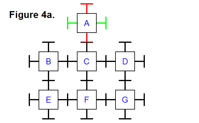
It is possible to transfer module A from row 1, column 2 to row 1, column 3, along the top surface of the rest of the matrix. Figure 4b, below, shows the same modules in Figure 4a, except that module A has been tilted by pivoting its bottom leg and the top leg of module C. The leg to the right of module A and the top leg of module D have also pivoted so the plates on the legs of these modules can connect to each other. The legs that pivot can also be extended so the connecting modules can reach each other, if necessary.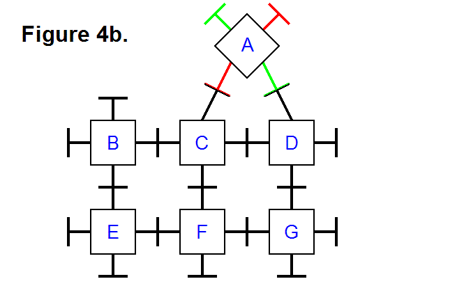
By reversing the motion of moving module A with module C and connecting it to module D, that is, disconnecting module A from module C and pivoting it upright with module D, module A is now in row 1, column 3; this is shown in Figure 4c, below.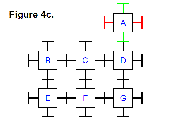
It is also possible to pivot a module around a corner of the matrix, such as with module A around module D from its top to its right side (position row 1, column 3 to position row 2, column 4). Figure 4d, below, shows the legs that connect modules A and D (the top leg of module D and the bottom leg of module A from Figure 4c) pivoted to allow the right leg of module D to pivot and connect to the bottom leg of module A (the same leg that was on the right side of module A in Figure 4c.), which was also pivoted into position for connecting to the leg from module D.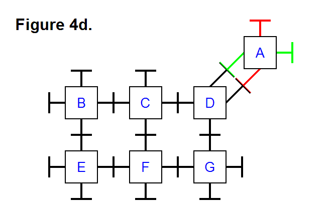
Finally, just as reversing the movement pattern halfway through the process of transferring module A from position row 1, column 2 to position row 1, column 3 could be used to accomplish that process in Figures 4a, 4b, and 4c, the same concept can also be applied to transferring module A from position row 1, column 3 to position row 2, column 4. Figure 4e shows the final result with module A in position row 2, column 4.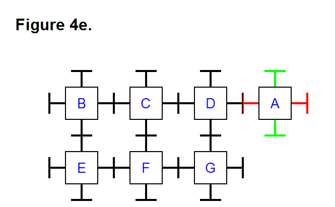
At this point it’s trivial to determine that module A can travel all the way around the rest of the matrix of modules B, C, D, E, F, and G, back to its initial position, by repeatedly applying the basic techniques of transferring a module along a row from one column to another, as well as around corners. Transferring a module vertically from one row to another in the same column involves using the same technique as transferring a module from one column to another column in the same row. In general, any module can be positioned to any other location to reshape either a 2-dimensional or 3-dimensional matrix consisting of any number of modules into any combination of connected patterns. Figure 4b shows how the modules in a matrix are not limited to being connected in a rectangular cycle arrangment (e.g., the way modules B, C, E, and F form a cycle); they can also be connected in a triangular cycle arrangement (e.g., the way modules A, C, and D form a cycle). Notice, also, that in Figure 4d modules A and D are connected together with two pairs of legs each; by using this feature it is possible to connect a series of several modules in this way, to double the tension strength. In a 3-dimensional matrix of modules, up to three pairs of legs can be connected between modules to triple the tension strength in a series of modules that are connected together in this way, since there are 6 legs for each module (instead of just 4 legs for each module as in a 2-dimensional matrix).
