ALIGNING LEGS FOR JOINING CONNECTING PLATES
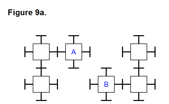
To join together two modules that are not aligned, in positions where all that is necessary is to extend the appropriate legs, both of these legs have to pivot to the correct angle. Figure 9a, shown below, is an example of two modules A and B that are not connected directly to each other in a matrix.
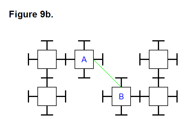
Suppose the right leg of module A and top leg of module B are selected for connecting these modules together. Figure 9b, shown below, shows the common axis along which these legs must align for connection as a green line.
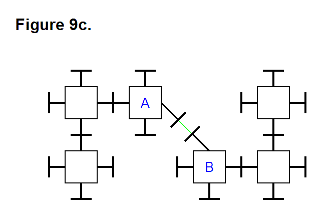
Figure 9c, shown below, shows the legs for modules A and B in new positions after they have pivoted to the angle to align them to their common axis, shown as a green line, for joining together.
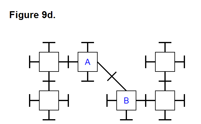
These legs are now aligned so that all that is is necessary for modules A and D to join together is to extend the legs. Figure 9d, shown below, shows modules A and B joined together after the legs have been extended.
If modules A and B are in the same matrix system and approximal, then it is not necessary to use any sensors or external input data to determine that the legs are aligned for joining. If modules A and B are in different matrix systems or a significant enough distance apart to be able to geometrically introduce an alignment discrepancy in the same matrix system, then it is necessary to use sensors or external input data to determine that the legs are aligned for joining; this can be accomplished by placing several sensors on the surface of the connecting plate and a significant distance from the axis of the leg and connecting plate, near the perimeter of the connecting plate circle. Once they are in close enough proximity to detect the presence of each other by emitting signature signals, the differences in strength of the signals determines whether or not the legs need to pivot until the signal strengths are equal to each other. This is usually a basic “reflex” action; an exception would be when the legs reach their pivoting limit. This pivoting limit is a minimum of 45° in any direction from the center axis perpendicular to the face of the module core assembly, or core “cube,” and will probably not be more than a few degrees beyond this because of the limitations imposed by the design of the module’s mechanical structures. In a situation where the legs cannot pivot to align to their common axis, the modules can still join together by carrying out more complex movements involving having the matrices change the positions of these modules and other modules that are adjacent to them in such a way that they can join together.
