DETERMINING THE DISTANCE BETWEEN THE CENTERS OF TWO CELLS CONNECTED TOGETHER
The geometric structural topology of a full cell consists of it having the following fundamental characteristics:
- the distance between the center of a cell and the point at which each leg pivots is a constant value
- for each cube face, the distances between the center of a cell and the point at which each leg pivots are all equal to each other
- for each cube face, the line segment between the center of a cell and the point at which each leg pivots is perpendicular to the line segments corresponding to each of the four adjacent cube faces
Many other characteristics about the topology of a cell can be derived from these fundamental characteristics and geometry. An essential key for a mesh of cells to form into objects is knowing its fundamental geometric structural topology and the distance between the centers of two cells connected together; this can be derived given that the following information is known about the modules in each cell that connect the two cells together:
- the length of the telescoping leg (this value is a variable within a fixed range)
- the angle a leg is pivoted, given as a value from a position perpendicular to the face of the cube; the absolute value of the angle a leg is pivoted will not be more than somewhere in the vicinity of 60 degrees
- either the actual connecting plate relative angle of rotation or the virtual connecting plate relative angle of rotation (i.e., derived from the effect of pivoting a leg about both of its cube face-oriented pivoting axes)
Figure 20a shows two cells connected together using a similar illustration convention as shown in Figure 12a from the article Geometrical Cell Dimension Limits and Requirements.
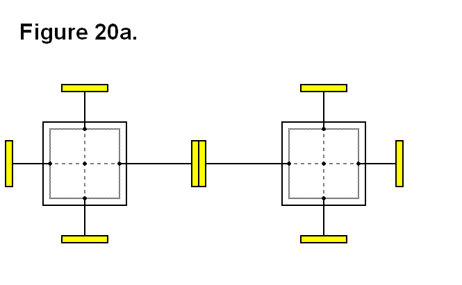
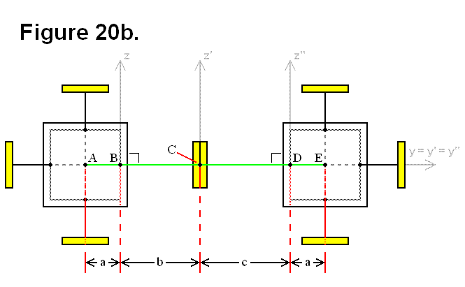
Figure 20b shows the same two cells connected together from Figure 20a including some 2-dimensional cartesian axes, labels for certain points, and labels for distance between these points. For the cartesian axes, the y, y’, and y” (from here on a dimension shall be generalized in the form w(n)) axes are all parallel and aligned along the y-dimension origin; the x(n) (for a 3rd dimension, shown in Figure 20e) and z(n) axes are all parallel to their corresponding dimensions. The legs that connect two cells together are always parallel and aligned about their axes; in Figure 20b they are aligned parallel to the y(n) axes and with the z(n) axes origins. The z’-axis is aligned to be centered at point C. The z-axis and z”-axis are arranged to be placed in alignment with the leg pivoting points B and D, respectively. In this case, both legs have pivot angle values of 0. Points A and E are the centers of their corresponding cells. Points B and D are the points at which each corresponding leg pivots. Point C is the center of the two connecting plates that are connected together. The distance between points A and B is the constant value a, which is equal to the distance between points D and E; this value corresponds to the distance described by the first list shown above, the fundamental geometric structural topology characteristics. The length of the telescoping leg from the left cell is b, which is the distance between the points B and C. The length of the telescoping leg from the right cell is c, which is the distance between the points Cand D. These leg lengths correspond to the first piece of information from the second list shown above.
In this case, determining the distance r between the centers of each cell is straighforward:
| |
(Formula #1) |
In Figure 20c, the labelled points and corresponding distance labels of Figure 20b are shown without the cell body diagram illustrations and with one of the legs pivoted an angular value of α.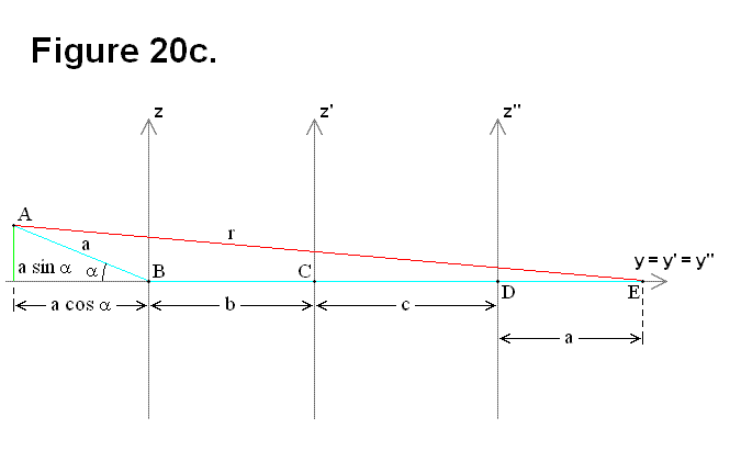
In this case the distance r between the centers of each cell is computed using the following equations and formula:
| |
(Formula #1a) |
| |
(Formula #1b) |
 |
(Formula #2) |
In Figure 20d, both legs are pivoted about parallel normal vectors, meaning all the labelled points (A, B, C, D, and E) lie on the same plane, thus only a 2-dimensional diagram is necessary for analysis; the second leg is pivoted with an angular value of β.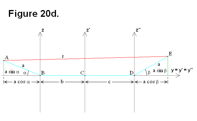
For this situation, calculating the distance r between the centers of each cell needs to be computed using the following equations and formula (Equation # 2b was plugged in) by either changing the definition of the angles to take a polar coordinate format about their corresponding origins, instead of being an absolute value format, or switching from plugging in Equation # 2b to plugging in Equation # 2c into Formula # 3 when the centers of the cells are on opposite sides of the z(n) axes from each other.
| |
(Formula #2a) |
| |
(Formula #2b) |
| |
(Formula #2c) |
 |
(Formula #3) |
In Figure 20e, not only are both legs pivoted about the y(n) axes, but also not all the labelled points (A, B, C, D, and E) have to lie on the same plane, thus a 3-dimensional diagram is necessary for analysis. The difference between Figure 20d and Figure 20e can be interpreted as a result of at least one of two reason:
- Connecting plate rotation took place between the two connecting plates connecting the cells together (at point C).
- Pivoting of one of the legs connecting the two cells together about the x(n)-y(n) plane took place.
The actual connecting plate relative angle of rotation or the virtual connecting plate relative angle of rotation (i.e., produced as a result of pivoting the legs) is the angular value f.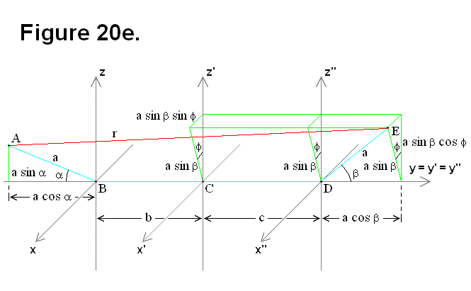
The following equations and formula are used to calculate the distance r between the centers of each cell for the case of Figure 20e. In this format the x(n)-component of the point A (the center of the cell on the left) is held fixed equal to 0. If necessary, as an intermediate step the modules can use the equations to derive calculated values and then re-apply those values to the formula using the same equations for calculating the distance r; this occurs when the pivot of the leg for the cell on the left is actually the resultant of the leg pivoting on both axes, when none of the legs on the faces adjacent to the legs connecting the cells together lie on the same plane, or when there is both leg pivoting and plate rotation. This principle is true for the apparent discrete cases of Figure 20d where all the labelled points (A, B, C, D, and E) happen to lie on the same plane; all that is necessary for this situation is to utilize the 3-dimensional approach for Figure 20e. It is not necessary to be concerned about whether or not the centers of the cells are on opposite sides of the z(n) axes from each other, as it was for the case of Figure 20d, because this is resolved by having equations for all 3 dimensions.
| |
(Formula #3a) |
| |
(Formula #3b) |
| |
(Formula #3c) |
 |
(Formula #4) |
In general, only Formula # 4 is needed to calculate r for all cases. By knowing the geometric structural topology of the cells, and for every cell the angle values α, β, f, the values for lengths a, b, c, and the distance between the centers of any two two cells r, a mesh of cells has all the information about cell positions and states that it needs for knowing the state of its structure, and it has the geometric information that is necessary for changing its shape.