CONNECTING PLATES ALIGNMENT REQUIREMENT
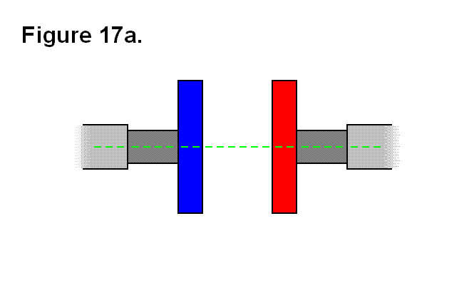
When the connecting plates of two different cells engage each other to connect to bond together correctly, the axis going though the center of each telescoping shaft and connecting plate have to be both parallel and aligned with each other; in other words, they both have to share a common axis. The reason this is necessary is to be able to utilize the entire area of the connecting plate of each module against moment forces, and large tension or compression forces along the telescoping shaft (module leg) axes. Figure 17a shows part of two telescoping shafts and side views of their connecting plates for two different modules; one of the connecting plates is blue and the other is red. The dashed green line through each telescoping shaft and connecting plate indicates the axis of the leg and connecting plate, and at the same time shows that they both share a common axis.
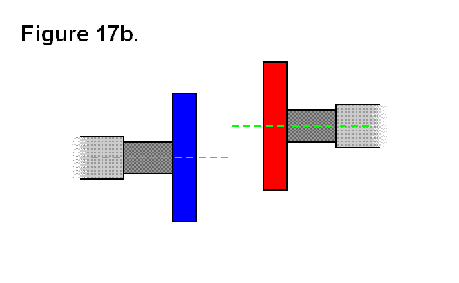
In figure 17b, the two legs and connecting plates of figure 17a are shown as parallel but not aligned to each other to share a common axis.
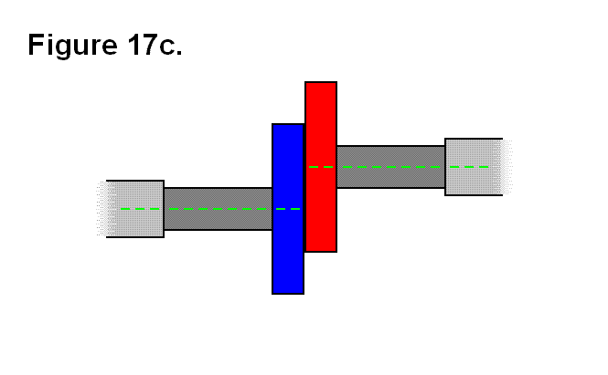
If the two connecting plates from figure 17b try to engage to bond together along their axes, they will come in contact as shown in figure 17c; since they aren’t aligned they won’t be able to bond, at least not properly if even possible at all. This type of contact is acceptable if it is not necessary for the two modules to bond together and if there isn’t going to be an excessive amount of force or pressure between them.
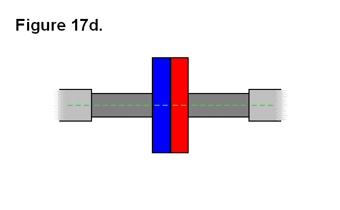
Figure 17d shows the two modules of figure 17a in contact for correctly connecting together; they might or might not be bonded together.
