MODULE CONNECTION ARRANGEMENT PATTERNS OF A CELL
A cell can be composed of a varying number modules, sometimes in various combinations for a given number of modules. When there can be various combinations for a given number of modules, there can be some arrangements that are not appropriate. Figure 19a shows 3 Core Base Assemblies, the objects consisting geometrically of two rectangular boxes and a square truncated pyramid with sides that slope at 45° angles that are part of the modules, connected together in such a way that they share a common corner. One of these modules has a gray shaded truncated pyramid for future reference. In this case the arrangement of modules is appropriate.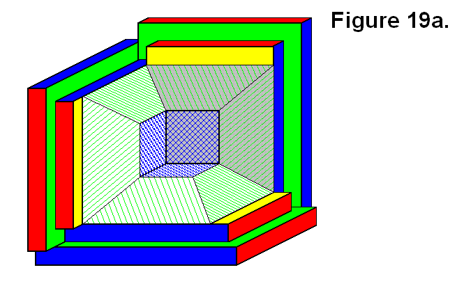
Figure 19b also shows 3 Core Base Assemblies connected together in such a way that they share a common corner, but they are a mirror image pattern of the 3 Core Base Assemblies of Figure 19a. This is also an appropriate arrangement of modules. The Core Base Assemblies of Figures 19a and 19b are opposite halves of a cell that can be joined together to form a whole cell.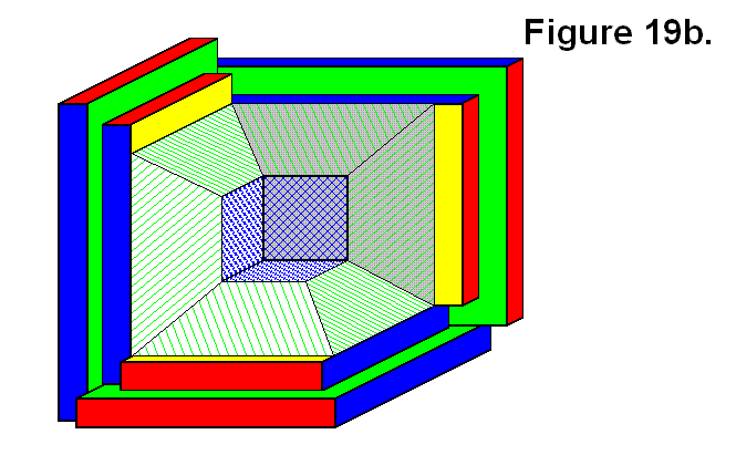
Figure 19c shows two modules connected together. This pattern is the only way any two modules can be joined together when there are only two; the bottom one can, for example, be assigned identification number 1 (ID #1) and the other would be assigned ID #2. There are four sides and two types of sides; the type of side is used as a reference to determine which has ID #1 or ID #2. If a third module is added to the pattern, using the Cube Face Numbering Convention article as a convention reference, then to Figure 19c the module with the gray pyramid in Figure 19b would be assigned ID #3; and in Figure 19a it would be assigned ID #4 since the first two modules are in reverse positions. Three of the arrangements of modules in Figure 19c can be joined together to form a whole cell.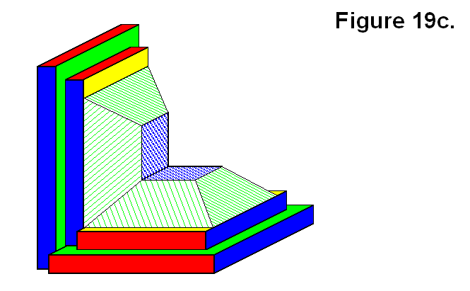
Figure 19d shows the same two modules of Figure 19c in a 2-dimensional side view.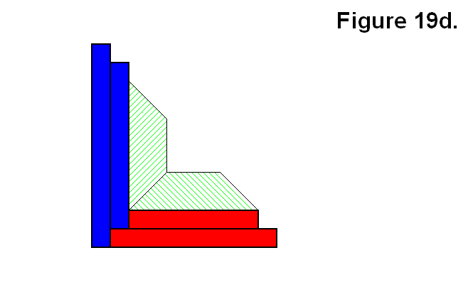
Figure 19e shows a third module added to the arrangement of modules from Figure 19d. This is not an appropriate arrangement of modules, and can be determined because there are more than two modules connected together and none of them share a common corner. One reason it is not appropriate is because if the pins-and-hole system that joins two modules together are not designed to latch the modules together (e.g., the pin is a simple cylinder), then this arrangement will not allow the modules to latch together to bond.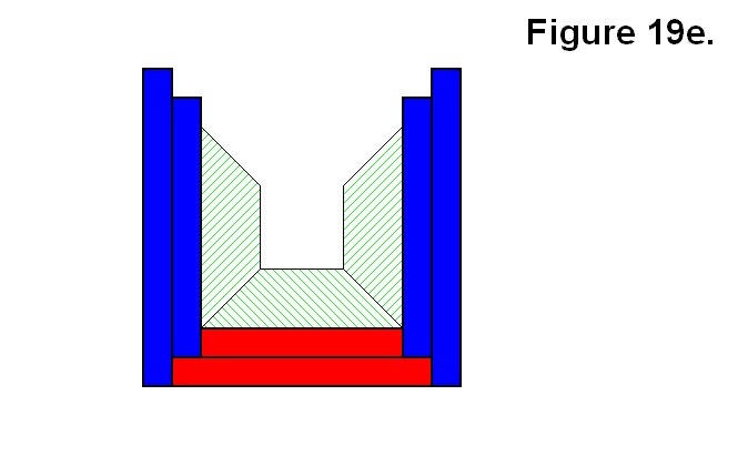
Figure 19f shows the arrangement of Figure 19e with a fourth module added to the back, shown partially out of view, in green, and with a gray pyramid. This arrangement of modules is appropriate, since each module shares a common corner with two of its adjacent modules. The arrangement of modules in Figure 19c can be joined to the arrangement of modules in Figure 19f to form a whole cell.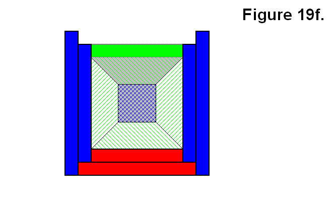
Figure 19g shows three modules arranged in the complementary arrangement of the ones in Figure 19e, and is also not an appropriate arrangement of modules for the same reason, and also because the two opposite modules won’t have the direct electronic connections described in the Pattern for Element Core Electronic Connections article. The two arrangements of modules in Figures 19e and 19g can join together to form a whole cell.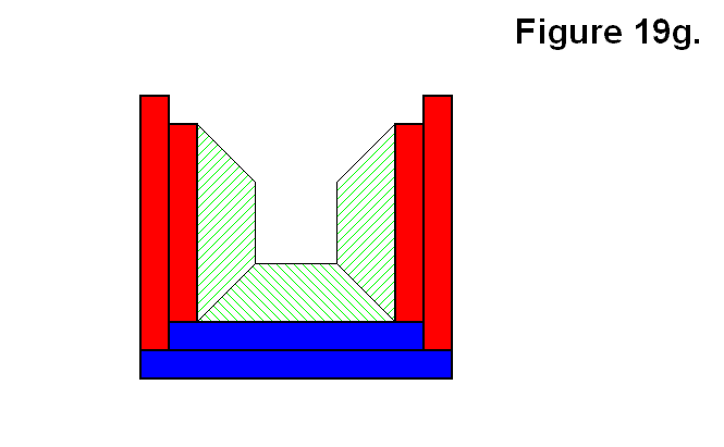
Figure 19h shows four modules in a ring pattern, and it is also not an appropriate arrangement of modules for the same reasons given for the three of Figure 19g.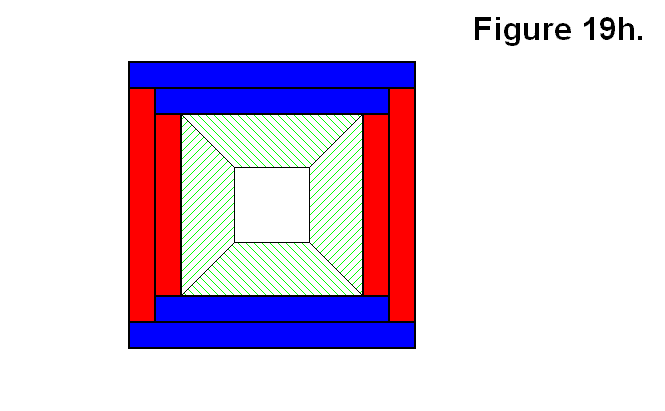
Although a fourth module with a gray pyramid is added, shown partially out of view and in green and yellow, to the arrangement of Figure 19g to form the arrangement of Figure 19i, there is no difference in the pattern arrangements of Figures 19i and 19f other than the gray one being in a different position in the pattern.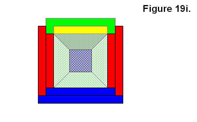
Figure 19j shows five modules connected together, made by connecting a fifth module to the top of the pattern of modules shown in figure 19i. This is the only way five modules can be connected together to form part of a cell. 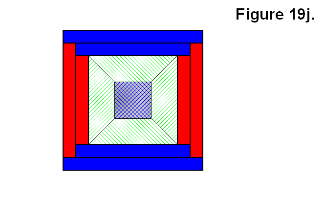
In Summary, the following table shows the possible number of arrangements for a given number of modules in a cell:
number of modules in a cell 2 3 4 5 6
possible number of arrangements 1 4 2 1 1
There are only two number-of-modules-in-a-cell situations where there are multiple possible number-of-arrangements of modules, for 3 and 4 modules. For 3 modules, 2 are appropriate and 2 are inappropriate; for 4 modules, 1 is appropriate and 1 is inappropriate.
