CELL STRUCTURE FORMING PATTERN POSSIBILITIES
There are several ways a module can be attached to other modules to form a partial cell, full cell, or inverse cell. In Figure 23a, the different side views of a single module is shown in various colors. The leg and connecting plate assembly is a darker blue, and the rest of the module is a different color for the type of side. For the opposite sides that are symmetric, the longer (lengthwise) side are green, and the shorter (widthwise) sides are red. The surface on which the leg mounts is light blue, and the opposite side is yellow. In this diagram, the truncated pyramid-shaped surface shown in this article: Module Connection Arrangement Patterns of a Cell is omitted, but the yellow side corresponds to the side on which it is mounted.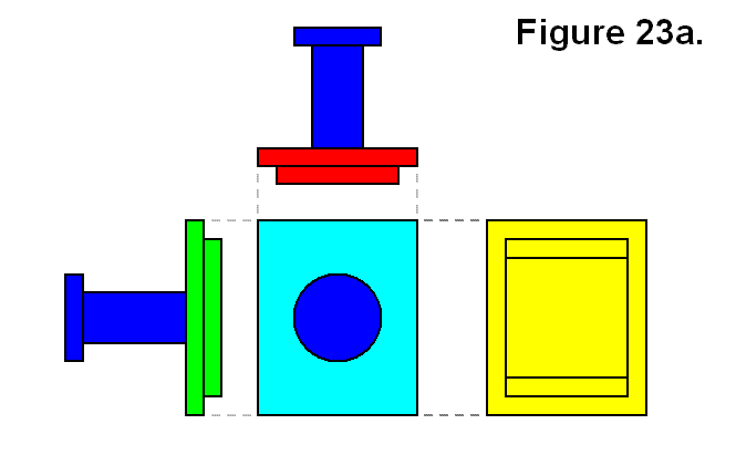
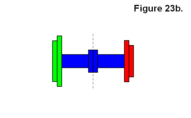
One type of connection of a module is to another single module via the connecting plates. This is shown in Figure 23b and is referred to as an “inverse cell.” The idea is that in the same way a mesh or matrix can be made of cells, and cells are made using modules, a mesh or matrix can also be made of inverse cells, and inverse cells can also be made using modules. In this figure, different colors do not necessarily signify different modules. Both the legs and the connecting plates of both modules are dark blue. On the left side of the line indicated by a vertical series of gray dashes is one module with a green lengthwise side shown, and on the right the other module with a red widthwise side shown. It is not necessary for the opposite types of side indicated by red or green to be aligned with each other from the two modules or to be aligned in general. It is only shown this way to make it easier to identify each module. The different resulting patterns will be categorized with abstract codes as connection types. A single module will be categorized simply as M. The resulting module structure in Figure 23b will be categorized as connection type T.
An expression describing the connection will also be given in the forms F → R or R ← F, meaning “F can form R,” where R is the resulting form and F is an abstract representation of “X + Y,” which means the joining of object X to object Y, and it is commutative (i.e., X + Y and Y + X are interchangeable). The objects X and Y each can be either a module M or a partially constructed cell R.
Expression: M + M → T
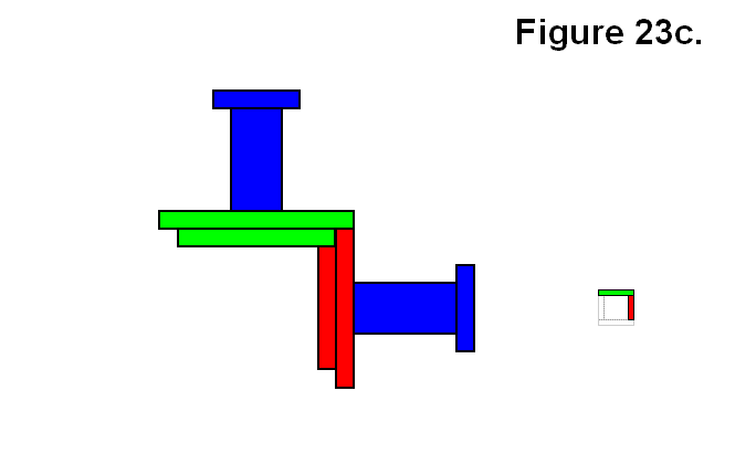
Another type of connection of a module M to another single module M is via the rectangular bases, which is to connect one along one of the green surfaces side (not shown) to the yellow widthwise side (not shown) of another in the type of orientation and alignment shown in Figure 23c. The smaller square to the right is an abstract icon representing the view angle of the figure with corresponding color pattern (shown for future reference). In this figure as well, different colors do not necessarily signify different modules. Both the legs and the connecting plates of both modules are dark blue. In this case it is necessary for the opposite types of side indicated by red or green to be aligned with each other from the two modules to be aligned. The different resulting patterns will be categorized with abstract codes as connection types. A single module will be categorized simply as M. The resulting module structure in Figure 23c will be categorized as connection type A. A formula describing the connection will also be given, for instance:
Expression: M + M → A
In the remaining part of this article the side views of the dark blue leg and connecting plate will be omitted from the diagrams and will only be limited to connections via the rectangular bases.
A single module can also be connected to a group made up of 2 to 5 modules connected together via their rectangular bases. Figure 23d shows one way of connecting a module M to each of a pair of modules A resulting in a partial cell in which all three modules share a common corner. The icon on the left is shown as a different angle than the figure image, and sometimes the view of the module in the back is obstructed by the one in front, so the gray circle with the smaller icons represent the side of the viewing direction of the figure (not present if viewing directions are the same) to reveal the presence of modules in the back on the icon. This resulting module structure will be categorized as connection type Bx.
Expression: A + M → Bx
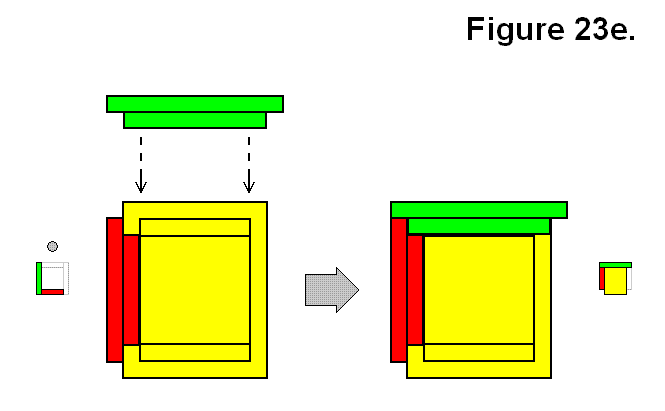
Figure 23e shows a reflective way a of connecting a module M to each of a pair of modules A resulting in a partial cell in which all three modules share a common corner, which is a mirror image of the version in Figure 23d. This resulting module structure will be categorized as connection type By.
Expression: A + M → By
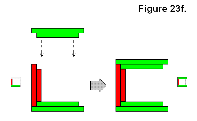
Instead of adding a single module M to a pair of modules resulting in a common corner, it can be added to one of the modules to be on the opposite side of the other module of an A structure. Figure 23f shows one version of this type of structure, categorized as connection type Ux.
Expression: A + M → Ux
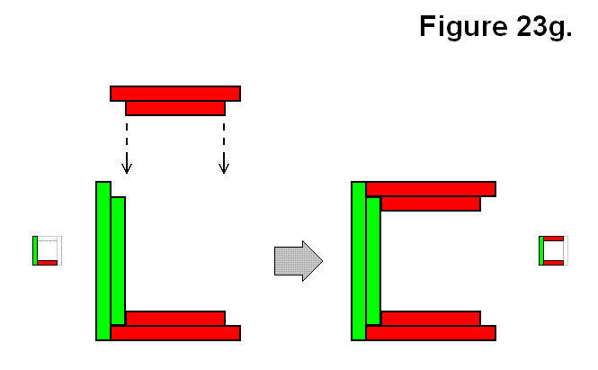
Figure 23g shows another version of the type of structure similar in arrangement pattern to the structure of Figure 23f using an M and A structure, categorized as connection type Uy. These two from Figures 23f and 23g are opposites to each other in that they can join together to form a full cell.
Expression: A + M → Uy
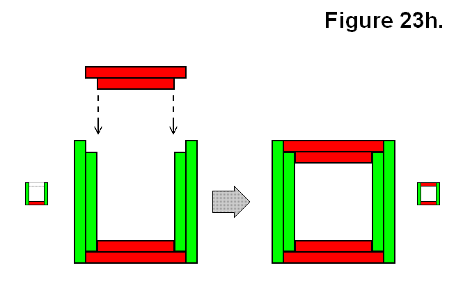
Another way in which a single module M can be connected to a group of multiple modules connected together via their rectangular bases is shown in Figure 23h, which is to connect it to a set of 3 modules in a Ux structure. This is one version that results in this pattern where the 4 modules joined together results in a 2D alternating cycled pattern, to be categorized as connection type O.
Expression: Ux + M → O
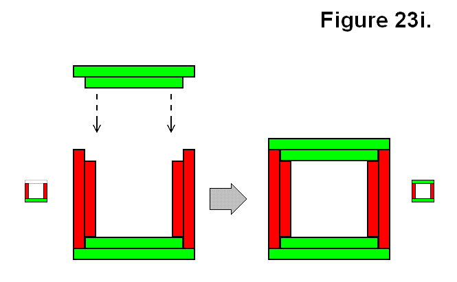
The other way to join a single module M to 3 other modules to result in connection type O is shown in Figure 23i, by using a Uystructure.
Expression: Uy + M → O
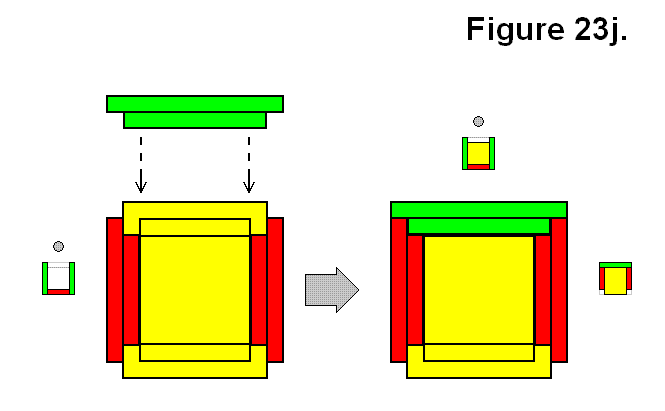
Another way to connect a module M to a set of 3 modules in a Ux structure is shown in Figure 23j. This is one version that results in a pattern where the 4 modules joined together do not result in the 2D alternating cycled patterns of Figures 23h and 23i, to be categorized as connection type G.
Expression: Ux + M → G
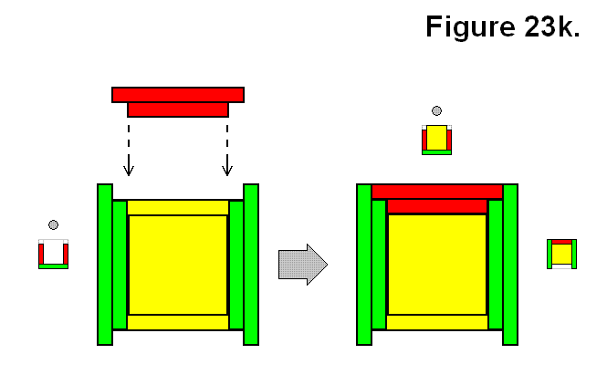
Figure 23k also shows another way to connect a module M to a set of 3 modules, which are in a Uy structure, resulting in a G structure.
Expression: Uy + M → G
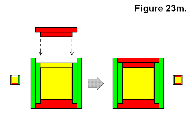
Another way in which a single module M can be connected to a group of multiple modules connected together via their rectangular bases is shown in Figure 23m, which is to connect it to a set of 4 modules in a G structure. This one is to be categorized as connection type Q.
Expression: G + M → Q
Figure 23n also shows another way to connect a module M to a set of 4 modules in a G structure which also results in a connection type Q.
Expression: G + M → Q
Figure 23o shows a way to connect a module M to a set of 4 modules in an O structure pattern for form a Q structure.
Expression: O + M → Q
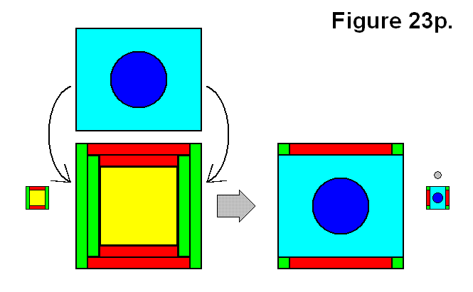
Figure 23p shows a full cell, categorized as connection type C, made by connecting a module M to a Q structure.
Expression: Q + M → C
 Forming a structure is not limited to being possible by adding just a module M to another structure. Two structures A and A can be joined together to form a structure. A structure O made by joining two structures A and A is shown in Figure 23q.
Expression: A + A → O
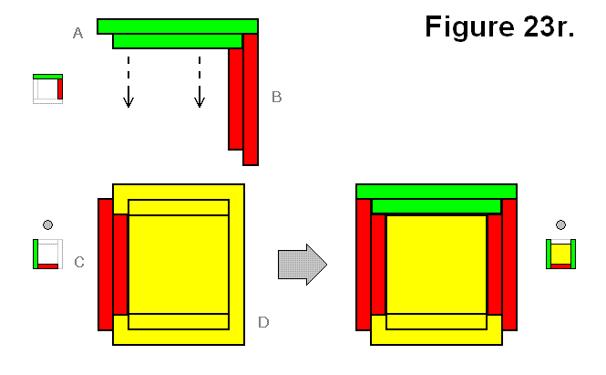
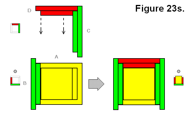
A structure G can be made by joining two structures A and A as shown in different perspectives in Figures 23r and 23s. Since it might not be simple to determine that different views are the same structure forming connection pattern, the modules are labeled A, B, C, and D to indicate which ones in Figure 23r can correspond to the ones in Figures 23s.
Expression: A + A → G
 |
 |
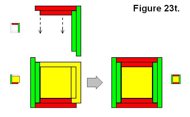
A structure Q can be made by joining two structures A and By as shown in Figure 23t.
Expression: A + By → Q
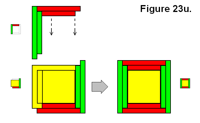
A structure Q can also be made by joining two structures A and Bx as shown in Figure 23u.
Expression: A + Bx → Q
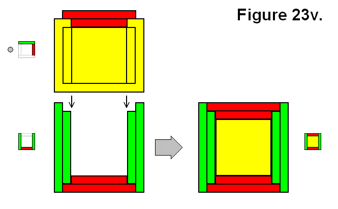
 A full cell structure Q can be made by joining two structures A and Ux as shown in Figure 23v.
Expression: A + Ux → Q
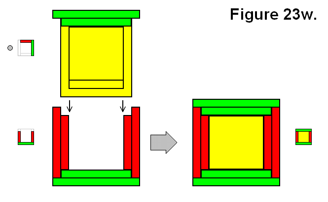
A full cell structure Q can also be made by joining two structures A and Uy as shown in Figure 23w.
Expression: A + Uy → Q
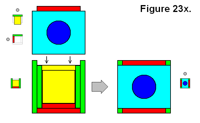
 A full cell structure C can be made by joining two structures A and G as shown in Figure 23x.
Expression: A + G → C
A full cell structure C can also be made by joining two symmetrically opposite B structures Bx and By as shown in Figure 23y.
Expression: Bx + By → C
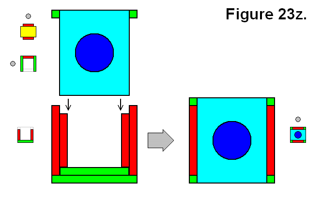
A full cell structure C can also be made by joining two symmetrically inverse U structures Ux and Uy as shown in Figure 23z.
Expression: Ux + Uy → C
The following table summarizes the expressions, and groups each connection F with matching results R or vice versa by separating each possible type of joining connection or result by a “|” symbol (meaning “or”), listed by number of modules in the resulting cell. If the subscript is omitted it means all versions are included.
|
||||||||||||||||||||||||||||||||||||||||||||||||||||||||||||||||
The following table summarizes the distinct possible “|” separated R result patterns arranged in order of number of modules in each joining part.
|
||||||||||||||||||||||||||||||||||||||||||||||||||||||||||||||||||||||||||||||||||||||||||||||||||||||||||||||||||||||||||

