THE CANTILEVER AND A BENEFIT OF HAVING A LARGE-RADIUS CONNECTING PLATE
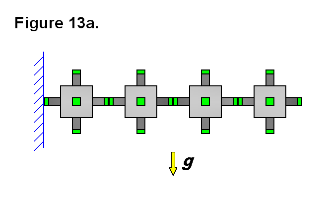
In some applications it is necessary to be able to form cantilevers with the modules; to form a cantilever requires several modules to be connected in series horizontally. Figure 13a shows a row of four modules with small connecting ends, in green, joined together in a row and mounted on the left side to a wall, in blue; gravity g, represented as a yellow arrow, is a force pulling downward. The connection between the left module and the other three modules is limited in strength between the connecting ends on either side, and is under tremendous stress as the axis for a moment of force introduced by the three modules on the right and gravity; this limits the number of modules that can be joined horizontally before these connecting ends fail.
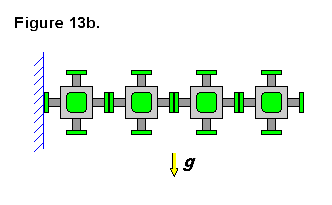
By simply increasing the radius of the connecting end from r = 1 unit to r = R units, the area of the connecting plate surface is increased by a ratio of R2 units (of area to 1 unit of area). Figure 13b shows the four modules, from Figure 13a, with larger radius connecting plates. The axis of the moment of force between the left module and the other three modules also moves closer to the top of the connecting plates and allows the area under that point between the connecting plates to help support the cantilevered row of modules. These features increase the limit of the number of modules that can be joined horizontally.
For the same reasons, the modules are limited in the length of the cantilever that they can produce by extending the legs that connect the modules together along the row; so a larger radius connecting plate also allows for longer rows of cantilevered modules. A feature that is provided by the actuated legs of the modules is the ability of the matrix to keep the cantilevered modules perfectly horizontal if necessary, rather than having the end of the cantilever droop downward.


