Terminology

TERMINOLOGY

This terminology does not necessarily adhere to strict technical formality. It is only meant to serve as a reference guide for standardization of their use in the articles. Some of the older versions of articles do not yet comply with this standardization. 

TERM WORKING DEFINITION OR EXPLANATION
cell a collection of between two to six modules connected to each other via their rectangular bases a matrix element made up of at least three modules that are connected together in such a way as to share a common corner of a partial cube
full cell a matrix element that consists of six modules and does not necessarily include a power cell; a cell that is not full consists of between 2 and 5 modules
complete cell a matrix element made up of six modules (a full cell) and a power cell
pseudo-cell a cell consisting of 2 modules
inverse cell two modules connected to each other via their connecting plates
matrix a group of modules or cells joined together primarily in a pattern
mesh a cell matrix made up of a random arrangement of connections and positions
module one of two fundamental elements that is a component in a matrix cell; an assembly of fabricated components; six modules make a full cell; this assembly consists of two ends connected together by a telescoping shaft, and contains moving parts, actuators, and electronics; one end is a connecting plate that can rotate about the axis of the telescoping shaft and can connect to the connecting plate of another module; the other (cell core fragment) end can connect directly to up to four other modules and a powercell (these four modules form a ring with the powercell in the center), to form the core of a cell, and a sixth module can connect to this core (on the “opposite side”) to form a full cell
powercell one of two fundamental elements that is a component in a matrix cell; a cube-shaped housing for an electrical battery; the position of the conductors on the face of the cubes are arranged in a symmetric pattern that prevents reverse polarity from being possible
module component one of the basic module assembly elements: the rectangular base, universal joint, telescoping shaft (leg), or connecting plate
module assembly a single module, made up of the module components

Benefits and Advantages

BENEFITS AND ADVANTAGES

  • Each cell in a mesh is capable of producing both translational and rotational motion. In each module there are three degrees of rotational freedom: rotation about the axis of the telescoping shaft, and pivoting the telescoping shaft in both (x & y axes) dimensions with a universal joint-like hinge system in the cell core fragment end of the module.
  • Any two cells, or modules, (they can either be part of the same mesh or in different meshes) that are within connecting distance from each other and have available connecting ends are capable of engaging each other in any positional and rotational orientations with respect to each other to connect together. This capability or feature can be a solution that would solve the problems of failed attempts for cells to interconnect correctly, or inability to connect because of alignment (design) limitations.
  • A mesh made up of these modules has the ability to independently replace the local power cells in a cell (i.e., without the need for any human intervention).
  • A mesh made up of these modules is capable of independently separating each module from a cell and assembling a cell from a supply of individual modules (i.e., without the need for any human intervention).
  • The connecting plate surface has electromagnets for short-term and quick connect and disconnect connections.
  • The connecting plate surface consists of a uniform pattern of hook and plunger mechanisms arranged close to the perimeter of the connecting plate surface for long-term unpowered connections.
  • Any connecting plate can connect to or couple with any other connecting plate from another module (e.g., like train couplers); the “male-female” pattern resides within the design of the hook-plunger mechanism rather than in the cells’ connector-to-connector system; this feature eliminates the constraint that limits or restricts cells’ abilities to have interconnections between any two cells when and where necessary.
  • The connecting plates have a relatively large diameter for providing static strength against gravity for a relatively larger series of approximately horizontal cells chained together which are mounted to a ground object (e.g., a cantilever system), such as a vertical wall, at one end; without this feature the connecting ends would bend or break off for some of the interconnections closest to the ground object, as a result of excessive stress due to large moment forces, with a relatively smaller series of approximately horizontal cells.

Cube Face Numbering Convention

CUBE FACE NUMBERING CONVENTION

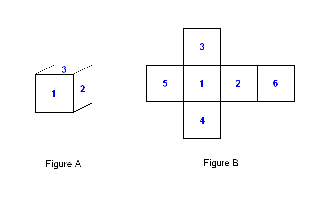
A number pattern convention can be used to identify modules when they are brought together to form a cell. In the Image below, Figure A shows a 3-dimensional cube with the faces that are showing numbered 1, 2, and 3 in a counter-clockwise direction about their common corner. Figure B shows the cube unfolded to indicate how all the faces of the cube are numbered in relation to each other. The numbering convention for determining which faces have values 4, 5, and 6 is to arrange them so that the sum of the values from each pair of opposite faces is equal to 7.

Components, Moving Parts, and Connectors of a Cell Module

COMPONENTS, MOVING PARTS, AND CONNECTORS OF A CELL MODULE

A cell module consists of several moving parts. There are 4 basic assemblies that make up a cell module, and each assembly consists of several components. The following is a list of the assemblies and the mechanical components of each assembly involved in the interaction between assemblies and modules (all assemblies consists of internal mechanical components that are not included here):

  1. connecting plate
    1. connecting plate hub: mounted on a segment of the telescoping shaft and can rotate about its axis
    2. connecting plate ring: consists of at least 3 hooks; mounted on the connecting plate hub, can independently rotate about the axis of the segment of the telescoping leg that is attached to the connecting plate hub, and can also translate along the axis of the leg upon the connecting plate hub
    3. at least 3 plungers, to pair up with the hooks on the connecting plate ring
  2. telescoping shaft (leg)
    1. segment with larger perimeter about axis at an extreme of a series of segments that connects to the intermediate joint and can pivot about one axis that it provides
    2. segment with smaller perimeter about axis at an extreme of a series of segments that connects to the connecting plate and allows it to rotate about the leg’s axis
    3. zero or more telescoping segments between the segments at the extremes
  3. intermediate joint (single component) assembly between leg and core base (acts as a universal joint)
  4. core base assembly
    1. core base assembly frame; has the basic appearance of a truncated pyramid mounted on top of a stack of rectangular slabs; consists of at least four holes to receive at least four pins, described below, along the perimeter surface of the bottom rectangular slab facing upwards (of the “basic appearance”)
    2. at least four pins that extend from the lengthwise sides of the core base frame
    3. 2 clamping teeth for gripping a power cell

The following list describes all of the types of assembly movements:

  • Leg pivoting: The leg can pivot about 2 axes within a range of at least 90° for each axis (±45° in any direction from axis perpendicular to the face of the cube-shaped nucleus formed by the 6 core base assembly frames when joined together).
  • Leg extending: The leg can both retract and extend to a length that more than doubles the (fully retracted) distance between the connecting plate surface and center of a six-module cell.
  • Connecting plate surface rotation: The connecting plate surface can rotate in both directions about the axis of the leg.

The following list describes all of the types of inter-modular connections:

  • Connecting plate surface interlocking system: The connecting plate surfaces of two different cell modules can engage and attach to to form a rigid bond or release from each other.
  • Core base assembly interlocking system: The core base assemblies can engage together to form a rigid core base structure or release from it.
  • Power cell grip: The power cell connecting surface on the core base assembly can grip and release power cells.

Types of Connections Between Elements

TYPES OF CONNECTIONS BETWEEN ELEMENTS

When two modules connect to, or just come in contact with, each other with the connecting plate surfaces, there are 3 ways this can happen. One way this can happen is if the surfaces only touch each other, but there is no interlocking bond; only pressure or stability are involved, and only pushing but not pulling can take place between the two modules. Another way this can happen is if there is a mechanical interlocking bond; this would be the prefereable means for long term or unpowered bonds. The last is if there is a powered electrical bond; if energy is removed, then the bond is broken; this would be the preferable means of bonding two modules in situations where connections have a very short duration and there is frequent connecting and disconnecting activity. A bond involving both mechanical and powered electrical means is possible and could be considered a fourth way, but in practice this would be extraneous or unnecessary (unless the interlocking mechanism is designed to be breakable by excessive tension and the powered electrical bond is necessary for providing more strengh).

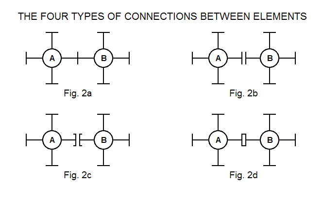
There are 4 types of schematic symbols for depicting 2 modules in contact with each other. In the image below, Figure 2a shows 2 modules A and B connected to each other without reference to the type of bond; Figure 2b shows 2 modules A and B connected without either type of bond; Figure 2c shows 2 modules A and B connected with only a powered electrical bond; finally, Figure 2d shows 2 modules A and B connected with at least a mechanical bond (it either may or may not have a powered electrical bond).