Extending/Retracting Matrix Effect

EXTENDING/RETRACTING MATRIX EFFECT

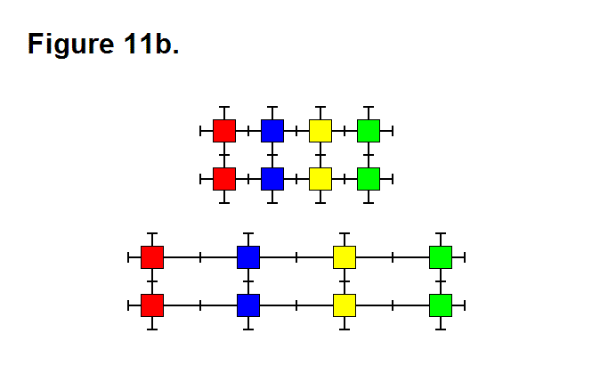
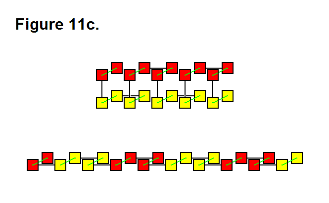
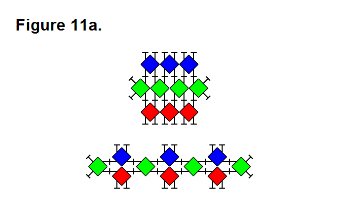
There are 3 basic means that a matrix can use to produce an extending or retracting effect; these are pivoting the legs (Figure 11a, below), telescoping the legs (Figure 11b, below), or rotating the connecting plate surface (Figure 11c, below). They can be performed in any combination with each other, and using all of them can be used to maximize the ratio between highest and lowest matrix densities. In the figures below, the upper image shows the matrix retracted and the lower image shows the matrix extended. In Figure 11c, the legs with the connecting plates that rotate are shown in green between the module cores (red and yellow rectangles) in a 2-layer 3-dimensional representation; for the upper image, the red modules are in the upper rows and the yellow modules are in the lower rows.


Matrix Production of Rotational Motion

MATRIX PRODUCTION OF ROTATIONAL MOTION

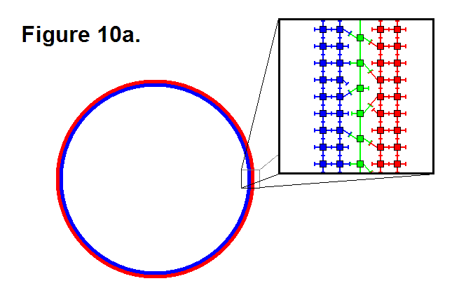
A matrix consisting of a large quantity of modules is capable of producing rotational motion. Figure 10a, shown below, shows a matrix in a ring configuration to produce this effect. It consists of an outer ring in red, and an inner ring in blue. It can be more than one ring layer of modules thick. The box shows an enlarged “under the microscope” view of the individual modules that make up a portion of the ring matrix. The center column, in green, consists of modules that repeatedly connect and disconnect to the red and blue columns of modules and forms a ring layer in the matrix between the red and blue rings. For the red ring to produce a clockwise rotation motion in the blue ring, the legs on the modules in the green column and on the modules in the columns on either side of the green column that connect to the green column pivot clockwise when not connected together and counter-clockwise when connected together. They do the reverse to produce a counter-clockwise rotational motion in the red ring.

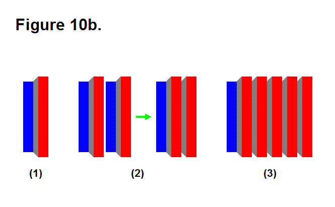
The maximum rotational speed produced by this matrix structure is fairly slow; for example, suppose that it has a radius of 10 feet; it will hypothetically only be able to produce 1 cycle per minute of rotational motion (or 1 RPM). By connecting several matrices of rings together in series in a certain way the angular speed can be doubled for each additional layer. Figure 10b, shown below, shows a matrix in image (1) consisting of two cylinders in red and blue connected together by a truncated cone section in gray. This matrix structure by itself does not produce rotational motion; it is a rigid object. Image (2) shows how two matrix objects structured this way can combine to form another complex matrix structure that layers the blue section for the matrix on the right in the red section of the matrix on the left to produce rotational motion, which corresponds to the matrix in Figure 10a. The five matrices connected together in series in image (3) have 4 layers that can produce a relative rotational speed that is 8 times the rotational speed of a single layer of 2 matrices connected together between the matrix structures at the ends of this complex matrix structure. The calculation is 25-2 = 8, where the 5 is the number of matrix structures and the rest of the numbers are constants. If 1 layer is capable of producing a maximum of 1 rotation per minute, then 4 layers is capable of producing 8 rotations per minute and 12 layers is capable of producing somewhere in the vicinity of two thousand rotations per minute (hypothetically, 2,048 RPM).

In general, the hypothetical formula for the total maximum rotational speed output is

sn-1 = 2n-2∙s1

where sn-1 is the total maximum rotational speed, n is the number (greater than 1) of matrix structure objects such as the one in image (1) of Figure 10b, and s1 is the maximum rotational speed output of two of these matrix structure objects. This means a very large rotational speed can be produced by having many matrices that produce rotational motion in series, but this is limited by the tension produced by the centrifugal forces in the matrices that are rotating at faster speeds. Factors such as radius, density of the modules (mass), friction from wind resistance, and maximum tension that the modules can handle have to be taken into consideration to determine the actual upper limit of sn.

Making Accelerometers Using Modules in a Matrix

MAKING ACCELEROMETERS USING MODULES IN A MATRIX

Although the modules can be produced so that each one has its own accelerometer, it is perhaps better that this option not be utilized, especially for matrices that would consist of large numbers of modules, for the following reasons:

  1. It is more expensive to mount an accelerometer element in each module.
  2. Generally it is unnecessary for a matrix to consist of modules that each contain an accelerometer.
  3. A matrix can build accelerometers that are located throughout the structure positioned where desired.

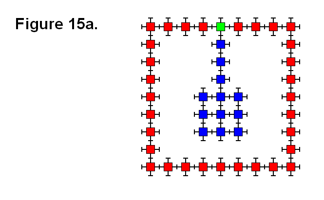
In Figure 15a, the matrix is a simple example of a structure with a pendulum, the blue modules, for an accelerometer. The red modules symbolize a simplified cross section of an implemented structure. When the structure is subjected to horizontal acceleration, the pendulum, which is connected to the rest of the structure by the green module, will pivot the leg of the green module to which it is connected and in neutral (i.e., it is not locked from moving). The green module’s leg, which is connected to the pendulum, uses the sensors for measuring the angle of the leg’s position to measure acceleration of the structure in the horizontal plane.

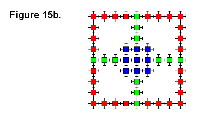
Figure 15b shows how a matrix can build a gravimeter. As the structure, which is shown simplified as the red shaded modules and in 2 of 3 dimensions, is subjected to forces, the block of blue modules affect the green modules that connect it to the rest of the structure. In a similar way that the leg of the green module is driven by the pendulum in Figure 15a to act as a sensor, the green modules in Figure 15b also use the pivoting and telescoping position sensors in their legs that are chained together to measure forces placed on the structure. An actual gravimeter would consist of having a 3rd row of green modules perpendicular to the plane of the image and connected to a 3-dimensional block of the blue shaded modules. The forces that it measures can be both translational as well as rotational. Since the effects of external forces are conservative, it is necessary for the green modules to implement feedback systems that poll for the actual presence of forces by measuring the resisting effect of actuating the leg. For example, when the external forces are removed, the green modules have to re-center the block of blue modules for “synthesizing” the effect of equilibrium.

In practice, a matrix implemented into a structure can randomly use almost any module “on-the-fly” as an accelerometer. This basically means that any matrix implemented into a structure practically has the inherent built-in feature of having accelerometers, even though there are no elements present in the modules designed to function as accelerometers.