Structure of a Sub-Module

STRUCTURE OF A SUB-MODULE

The Sub-Modules are assemblies that connect together to form Macro-Modules, and these Macro-Modules then connect to each other to form application structures. These Sub-Modules are all identical to each other in all aspects of structure (e.g., mechanically, electronically, operationally). They consist of two different types of bases and a leg. One of the bases is a Core Base Assembly (the “core” being the “nucleus” of the Macro-Module) and the other is the Connecting Plate Assembly. The Core Base Assembly is linked to the Connecting Plate Assembly by a Leg Assembly that can extend and retract. The Core Base Assembly can pivot the Leg Assembly about both axes which are perpendicular to the axis of the Leg Assembly (i.e., it can pivot in any direction just as an arm can pivot being mounted on the shoulder). The Connecting Plate Assembly can rotate in either clockwise or counter-clockwise directions about the axis of the leg. There are two ways the Sub-Modules can connect to each other. One involves the Core Base Assembly; this means of connecting involves connecting each one directly to four others and indirectly to a fifth one to form into a Macro-Module. The other involves the Connecting Plate Assembly; the Macro-Modules connect to each other by using this as a means for connecting together. The Core Base Assemblies can encase a Power Cell that can optionally be present or absent. The Sub-Modules can transmit and receive power and communication signals. If a Macro-Module doesn’t contain a Power Cell then it must utilize adjacent modules to acquire energy.

Figure 8a, below shows 3 views of the Core Base Assembly. It consists geometrically of two rectangular boxes and a square Truncated Pyramid with sides that slope at 45° angles. The rectangular boxes are of the same thickness, but one, shown as the External Block Region in the figure, has a perimeter that is larger than the other, shown as the Internal Block Region in the figure, of a thickness equal to their box thicknesses (the thickness that each rectangular box has in common with each other of being equal in length on those sides). The two rectangular boxes join together such that their centers are aligned and the box thickness perimeter of the larger rectangle circumscribes the smaller rectangle. The pyramid is of a size such that the edges of two opposite sides of the larger end of the pyramid meet flush with the smaller rectangle and have a space on the other two opposite sides that form space on either side of the surface of the smaller rectangle that are also equal in thickness to the box thicknesses of the rectangle shapes. The smaller end of the pyramid is a Connecting Plane for a cube-shaped Power Cell, also shown in the figure. This shape is necessary to allow the Sub-Modules to connect together in a specific pattern. The larger rectangle houses Connecting Points, which consist of pins and holes that are used to bond the Core Base Assemblies together. The Inward Side view is a view of the side that goes into the core of the Macro-Module.
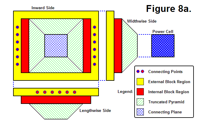
 

Figure 8b, shown below, also shows 3 views of the Core Base Assembly, except that one of them is an Outward Side view. The Core Base Assembly actually consists of 2 moving parts, an Outer Sub-Module Assembly and an Inner Sub-Module Assembly. This Inner Sub-Module Assembly houses actuators and acts as a universal joint between the Outer Sub-Module Assembly and Leg Assembly that gives it the ability to pivot about both axes. The Perimeter of the Inner Sub-Module Assembly is shown within the Outward Side view of the Core Base Assembly shaded in blue; the rest of the view and the other side views show the region of the Outer Sub-Module Assembly. The Pyramid Well is the region that can be seen behind the Inner Sub-Module Assembly in the Outward Side view, which is a view of the inside of the Truncated Pyramid.
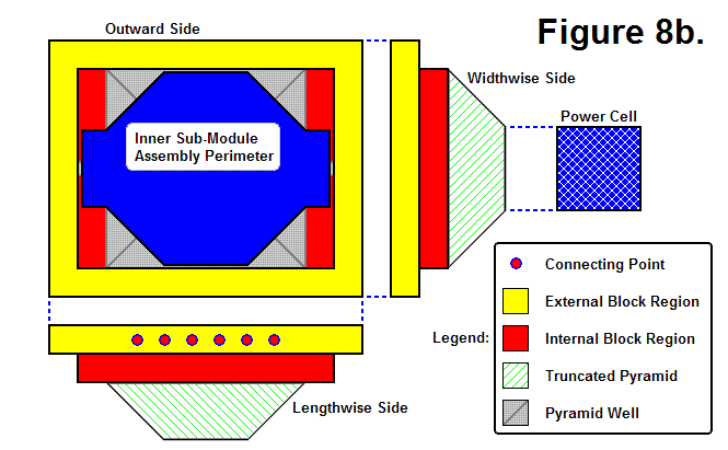
Figure 8c, shown below, shows 4 Core Base Assemblies and a Power Cell aligned to geometrically join together. 
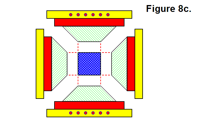
Figure 8d, shown below, shows the 4 Core Base Assemblies and Power Cell from Figure 8c geometrically joined together such that the 4 Core Base Assemblies encompass the Power Cell.
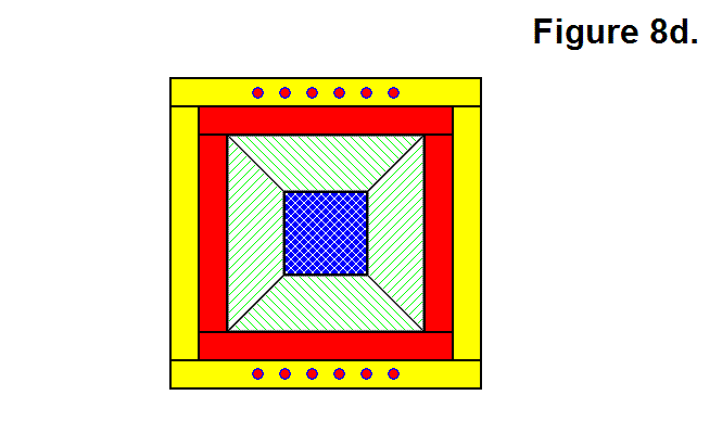
Figure 8e, shown below, shows 5 Core Base Assemblies connected together.
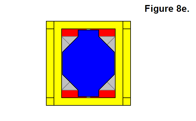
Figure 8f, shown below, shows a 3-dimensional view of 2 Core Base Assemblies geometrically joined together.
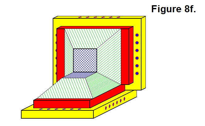
Figure 8g, shown below, shows a 3-dimensional view of 3 Core Base Assemblies connected together. Their geometric pattern, wherein they are sharing a common corner, mechanically bonds them together when the pin-and-hole system is engaged along the edges where another Sub-Module is present.
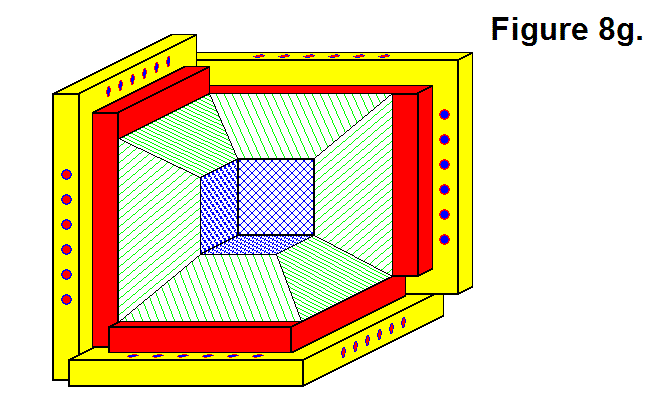
Figure 8h, shown below, shows the Inner Sub-Module Assembly contained within a wireframe outline of a transparent Outer Sub-Module Assembly. The Leg Space & Pivot Channel represents the perimeter of the space within the Inner Sub-Module Assembly in which the Leg Assembly is located and moves.
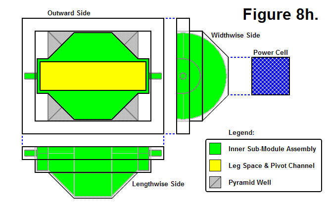
Figure 8i, shown below, shows a hypothetical end of part of the Leg Assembly contained within a wireframe outline of a transparent Inner Sub-Module Assembly. The Leg End Pivoting Range shows the space needed by the end of the Leg Assembly for pivoting.
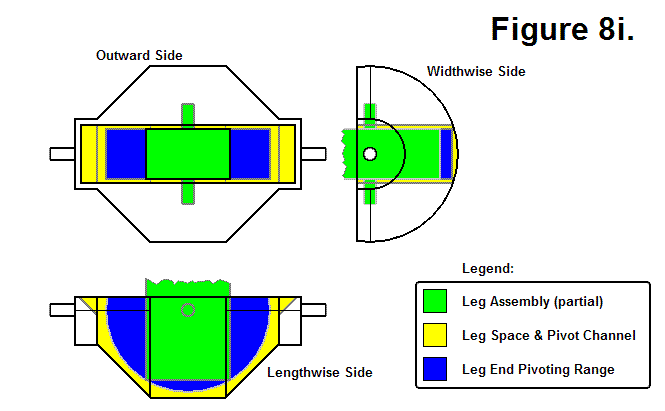
Figure 8j, shown below, shows a hypothetical Leg Assembly of undetermined length. It also shows the Connecting Plate Perimeter in relation to the Leg Assembly; the Connecting Plate and the Leg Assembly have the same center axis of symmetry, and the Connecting Plate can rotate about this axis. The Leg Assembly basically consists of a series of hollow tubes to allow it to extend and retract.
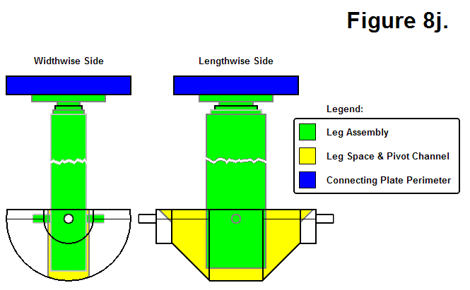
Figure 8k, shown below, shows the Connecting Plate Surface of the Connecting Plate Assembly. The Connecting Plate Arc Cross Section is a “side view” diagram of the Connecting Plate Assembly’s surface. The Connecting Plate Outer Ring serves as the mounting surface for the hooks and houses the plungers. This hook and plunger system acts as an interlocking mechanism between the two plates. The Connecting Plate Center Circle hypothetically serves as a region where electromagnets and communication components are housed.
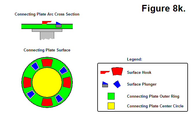
Figure 8m, shown below, shows how two Connecting Plates from different modules can connect together. States 1 through 6 show the Connecting Sequence of the two plates, and states 6 through 9 show the Disconnecting Sequence of the two plates. To connect, the red plate engages the blue plate by rotating to the left, as shown in sequences 1-5; in sequence 6 the plungers are extended out to lock the plates together. To disconnect, the plungers are retracted in, as shown in sequence 7, and the red plate disengages the blue plate by rotating to the right, as shown in sequences 8 and 9.
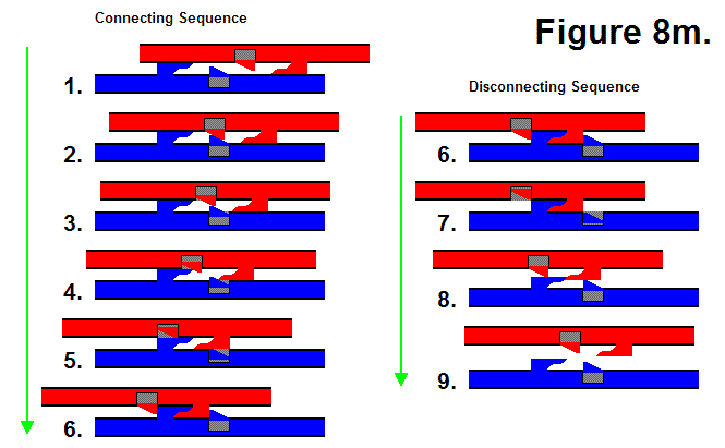
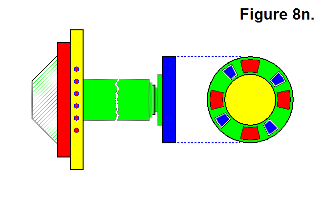
Figure 8n, shown below, shows a full Lengthwise Side view of a Sub-Module along with a Connecting Plate Surface view.
Leg Pivot Range Requirement

LEG PIVOT RANGE REQUIREMENT

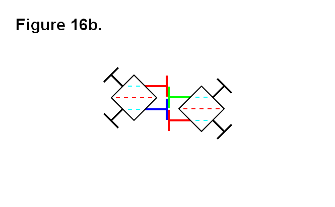
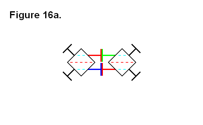
In the following figures, all the dashed lines are parallel to each other. The dashed red lines indicate imaginary lines between the two opposite corners of the cube-shaped nucleus, and the dashed light-blue lines indicate imaginary lines connecting the centers of the face of the cube-shaped nucleus, where the legs connect to them to pivot. Figure 16a shows how two modules connected together with 2 pairs of legs need the flexibility of the legs to be able to pivot at least 45° to the face of the cube-shaped nucleus.

Figure 16b shows a circumstance where the legs need to be able to pivot more than 45° in order for the two cells to connect together; it is the situation where the legs need to be able to pivot the furthest, which is determined by the dashed red lines being aligned with light blue dashed lines. The actual angle value is determined by how close the two cells can be to each other, and how close the two cells can be to each other is determined by the length of the fully retracted telescoping shaft (the leg) plus the thickness of the connecting plate.

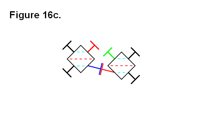
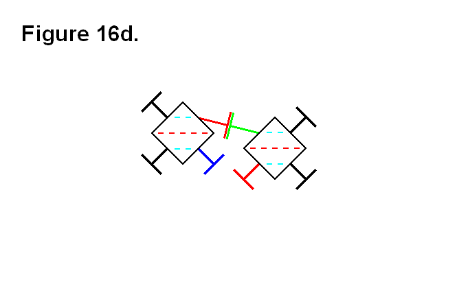
Figures 16c and 16d show one way (they’re both the same type of connection, one is an upside-down view of the other) for the two cells to connect together when they are in the positions of the cells in figure 16b. The closest the two cells can come to each other in this situation is a value that is proportional to the absolute value of the tangent function with the argument value of φ + 45°, where φ is the angle between the face of the cube and the leg that is less than 45°. The ideal leg pivot range angular limit orthogonal to the face of the cube to implement would be as close to around 60° as possible, because as the angle approaches 45° the distance approaches infinity (in an exponential growth-like rate); it is not necessary to go beyond a leg pivot angular limit of about 60°, because anything greater than that is an approximately linearly decreasing rate, and would require the unfeasible implementation of the legs (i.e., they would have to be extremely thin) and other components that would be affected.


Figures 16e shows the two cells from figure 16b connected together using both pairs of legs. This or the connection arrangements of figures 16c and 16d would be the choice for connecting the two cells together if the two red dashed lines from each cell are not going to extend, beyond the boundary indicated by the light-blue dashed line, to be any further apart from each other than this.

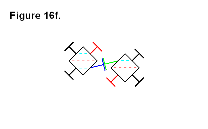
In figure 16f, the two cells from figure 16b are connected together in an alternative way to the way the cells are connected together in figures 16c and 16d. This connection arrangement would be the choice for connecting the two cells together if the two red dashed lines from each cell are going to extend, beyond the boundary indicated by the light-blue dashed line, to be any further apart from each other than this.

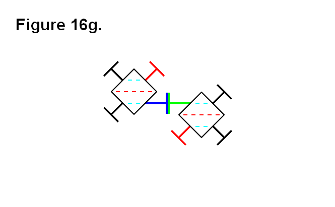
In figure 16g, the two cells are in positions where the two red dashed lines are farther apart, and the legs are back to being pivoted at 45° angles to the faces of the cube-shaped nuclei.

Leg Thickness Limits Based on Pivoting Ranges and Well Perimeter Edge

LEG THICKNESS LIMITS BASED ON PIVOTING RANGES AND WELL PERIMETER EDGE

The thickness of the outermost telescoping leg segment (the rectangular sides of a cross section) determines the leg’s pivoting range limit. For a thicker leg the pivoting range limit is smaller, and for a thinner leg the pivoting range limit is larger. The tradeoffs for a thicker leg include the following features:

  1. more strength against leg bending strain or damage
  2. more space for the mechanical system to telescope the leg
  3. more leg segments for telescoping the leg

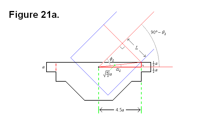
For both Figures 21a and 21b the variable a and the module core assembly base component ratios are based on the calculations from the Optimal Ratio Calculation for Module Core Assembly Base Component article.Figure 21a is a diagram of a lengthwise cross section of the base of the module that forms the module core assembly base component as a black outline and a representation of the boundary of the leg that can enter the well as a blue line. The lengthwise well perimeter is indicated by the red vertical lines. The variable L represents half the lengthwise thickness of the leg, and the variable θL represents the lengthwise plane of rotation angle for the leg from a perpendicular position relative to the face of the cell cube.

The following equations and calculations are derived from the geometrical information provided by Figure 21a:

                           (Equation #1)
                                                                                   (Equation #2)
(Formula #1)
                                                      (Formula #2)

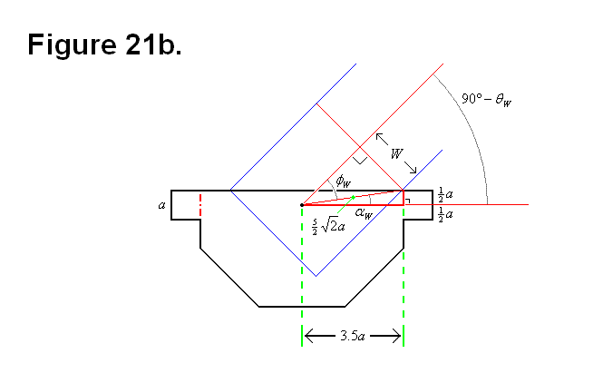
Figure 21b is a diagram of a widthwise cross section of the base of the module that forms the module core assembly base component as a black outline and a representation of the boundary of the leg that can enter the well as a blue line. The widthwise well perimeter is indicated by the red vertical lines. The variable W represents half the widthwise thickness of the leg, and the variable θW represents the widthwise plane of rotation angle for the leg from a perpendicular position relative to the face of the cell cube.

The following equations and calculations are derived from the geometrical information provided by Figure 21b:

                           (Equation #3)
                                                                                   (Equation #4)
(Formula #3)
                                                      (Formula #4)
Graph #1 Graph #2
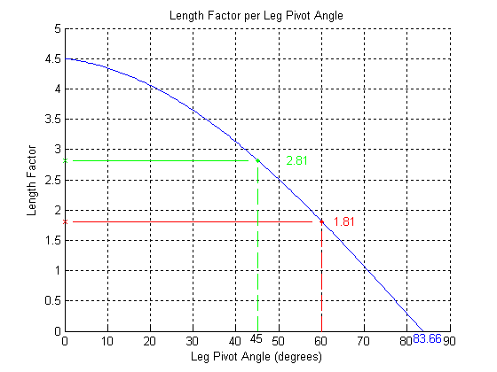
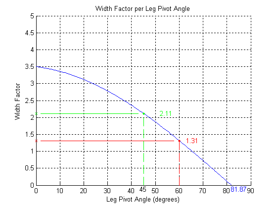
Graph # 1 shows a plot of the angle versus the rectangular lenghwise thickness factor (to ratio variable a) of the leg. Green is for an angle of 45 degrees, and red is for an angle of 60 degrees. Beyond 60 degrees the decrease is almost linear.

Graph # 2 shows a plot of the angle versus the rectangular widthwise thickness factor (to ratio variable a) of the leg. Green is for an angle of 45 degrees, and red is for an angle of 60 degrees. Beyond 60 degrees the decrease is almost linear.

Graphs # 1 and # 2 were generated using the following Matlab code: matlab.txt

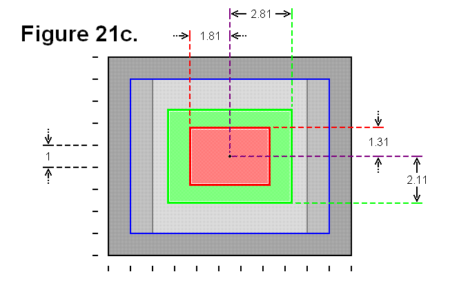
Figure 21c shows a view of the face of the module core assembly base component with the perimeter of the well as a blue rectangular line. The well perimeter and the surface plane of the face that it intersects with forms the well perimeter edge. The green rectangle represents the leg thickness and rectangular perimeter as a cross section of a leg that can pivot up to 45 degrees, and the red rectangle represents the leg thickness and rectangular perimeter as a cross section of a leg that can pivot up to 60 degrees.

In reality, the intermediate universal joint-like component between the module core assembly base component and the first segment of the leg will affect either the shape of the rectangle on the widthwise side of the leg or the shape of the well, because of the cylindrical twisting effect introduced by the universal joint-like component. Also, the universal joint-like component can also affect the lengthwise range, since it pivotally mounts to the module core assembly base component in the region the leg would enter in the well; this might be a limitation that can be minimized or eliminated with an appropriate design for the structure of this universal joint-like component.


Geometrical Cell Dimension Limits and Requirements

GEOMETRICAL CELL DIMENSION LIMITS AND REQUIREMENTS

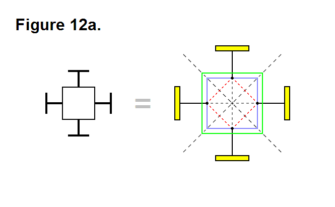
In order to be able to achieve some of the needed features and capabilies, there are some minimum requirements in length ratios and pivot angles which can be calculated. There are also certain constraints in length ratios imposed by the geometric shapes of the modules. Figure 12a shows equivalences of module schematics, a basic more symbolic version on the left side, and a more detailed image of a cell on the right side. The image on the right side is the one that will be used as a template for the subject matter of this article. The connecting plates (a side view) are shaded in yellow; the black lines going from the connecting plates to the inner blue square in the center represent the telescoping shafts (the legs). The points where the legs connect to the blue square is where the legs pivot about both axes (in this 2-dimensional image we shall only consider pivoting about the axis that is perpendicular to the plane of the image). The green square represents the perimeter of the cell nucleus, and are also side views of the faces of the cell nucleus. The dashed lines will be used for reference measurements.

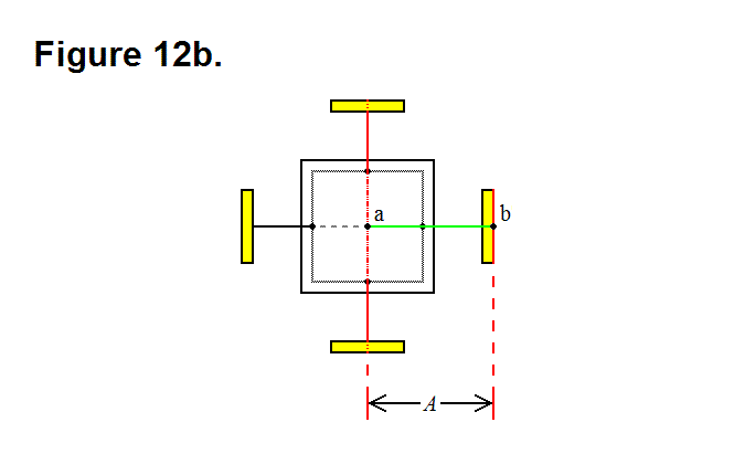
In Figure 12b the distance between points a (the center of the cell) and b (the point that intersects the surface of the connecting plate while the leg is completely retracted, and the leg axis) is equal to A; this line segment is shown as a green line.

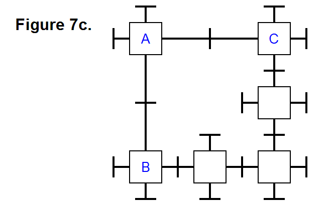
Recalling Figure 7c from the article Diagonal Lattice Reconfiguration Using Leg Extending Capabilities, in order to make it possible for the leg from module A to be able to reach and connect to module C, it is necessary that the legs be able to extend a distance that is long enough to span the distance imposed by the three modules in the bottom row, having module B on the left side, where the row legs that are connected together are fully retracted.

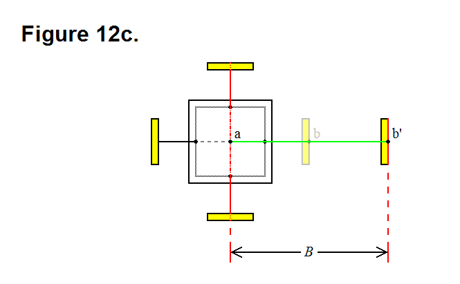
This length of the extended leg associated with this minimum requirement length is represented in Figure 12c as the distance between points a (the center of the cell) and b’ (the point that intersects the surface of the connecting plate while the leg is extended to meet the minimum length requirement, and the leg axis) is equal to B; this line segment is shown as a green line.

An equation can now be formulated; in the top row of Figure 7c, the distance between module A and module C is 2B; in the bottom row (starting with module B) of Figure 7c, the distance between the center of the modules on either end would be 4A. These two values, 2B and 4A, are related in the following way: 2B > 4A; by simlifying this equation the following equation is derived:

 B > 2A       (Equation 1)

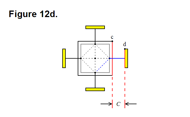
 In Figure 12d the leg axis component distance between points c (the corner of the nucleus perimeter) and d (the edge of the underside of the connecting plate while the leg is fully retracted) is equal to C; this corresponds to the distance between the face of the nucleus and the underside of the connecting plate while the leg is fully retracted.

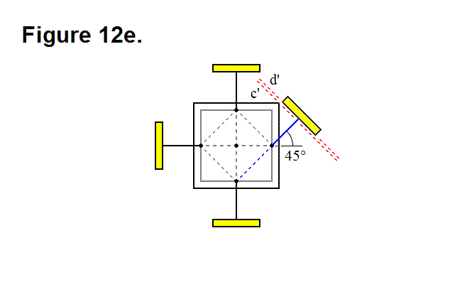
When the leg pivots 45 degrees, as shown in Figure 12e, the connecting plate edge comes close to the corner of the nucleus cube; if length C is not long enough then the connecting plate will strike the nucleus if it attempts to pivot 45 degrees, which will prevent it from being able to achieve this. The red dashed line c’ represents the orthogonal limit plane imposed by the corner of the nucleus, and the red dashed line d’ represents the underside plane of the connecting plate when the leg is fully retracted; these two planes can approach each other, but they cannot be intersecting.

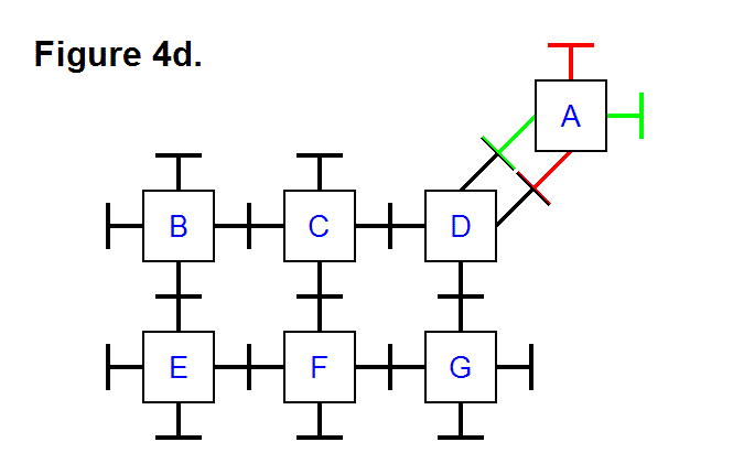
Recalling Figure 4d from the article Basic Module Transfers, Movements, and Connections, in order to make it possible for module A to be able to connect to module D with two adjacent legs from each module, not only it is necessary that the legs be able to pivot by at least 45 degrees, but it is also necessary that the radius of the connecting plates not reach a certain maximum limit

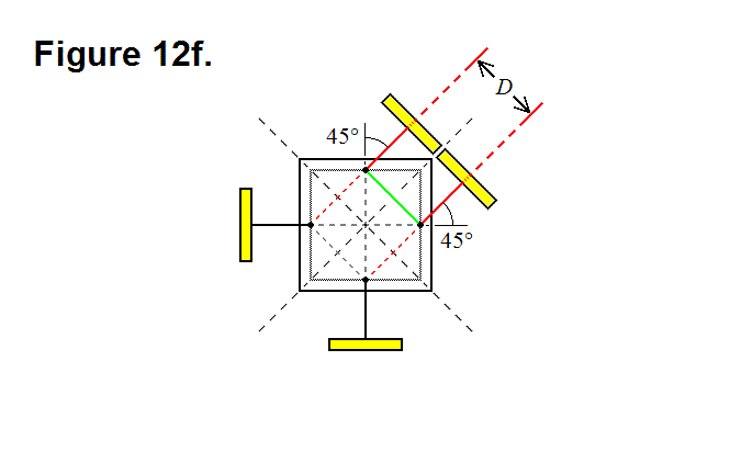
The distance between the center of the two connecting plates on the legs that are pivoted 45 degrees towards each other in Figure 12f is D (it is also equal to the line segment shown as a green line); based on this observation, the circumference of the connecting plate must be less than D, which means that the radius has to be less than D/2.

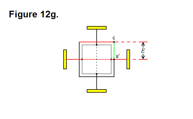
In Figure 12g the distance between points c (the corner of the nucleus) and a’ (the point that intersects the surface of the nucleus and the leg axis) is equal to E; this line segment is shown as a green line.

The length between the point where the leg pivots and the face of the nucleus along the axis of the leg is a/2 (see Optimal Ratio Calculation for Module Core Assembly Base Component); by using trigonometry, the following equation can be derived: D = √2(E-a/2). Solving for E produces the following equation:

E = (√2D + a)/2     (Equation 2)

This means that now we know that the radius of the connecting plate has to be less than √2(E-a/2)/2. With some trigonometry and geometric manipulations, and the fact that C has to result in the gap greater than zero between planes c’ and d’ in Figure 12e, the following equation can also be derived: 2C + a > D + √2a. By solving for C in this equation, the following equation can be derived:

C > (D+(√2-1)a)/2     (Equation 3)

If the thickness of the connecting plate along the leg axis is T, then the following equation relating length A to lengths C and Ecan be derived: A = C + E + T. By substituting for the values of C and E in this equation, the following equation can be derived: A < (D+(√2-1)a)/2 + (√2D + a)/2 + T; simplifying this equation produces:

A < ((√2 + 1)D + √2a)/2 + T     (Equation 4)


Pattern for Element Core Electronic Connections

PATTERN FOR ELEMENT CORE ELECTRONIC CONNECTIONS

The sub-modular entities in a basic level modular element need to be able to electronically connect to each other through their core bases, to transfer power or communicate with each other. In a full basic level modular element each entity can electronically connect directly to every other entity, except for the one on the opposite side, since they are adjacent to each other.

One way to make it possible for entities that are on opposite sides of each other to electronically connect is to provide a relay path through some of the adjacent entities; a relay channel needs to be present in every entity to accomplish this. Since the entities are uniformly manufactured, the relay paths can also be present in a uniform pattern.

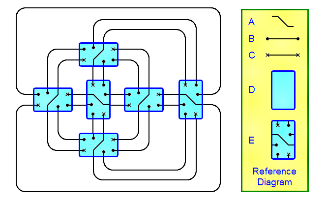
There is a simple way to implement this solution; the figure below is a schematic diagram showing how the entities can electronically connect to both the adjacent and opposite side entities. The yellow box contains entity core base components labeled A, B, C, D, and E. Component A is the symbol for an electronic relay path through an entity for connecting two entities that are opposite from each other. Component B is an electronic connection between two entities; the clubbed ends indicate the entities they electronically connect by being encased in the symbol for an entity, component D. Component C is similar to component B, except the ends are X-shaped and it emphasizes that it is a relayed path for electronically connecting entities that are opposite from each other. The path symbolized in component B is only an electronic connection, not a representation of the path through space (i.e., it is not a mechanical schematic). Component E is the symbolic pattern of the uniformity of each entity (they are also symmetric in 180 degree rotations); each entity in the schematic diagram has an identical pattern to it, if rotated by 90 degrees when necessary.

Adjacent entities have one electronic connection, but entities that are at opposite sides of each other have two electronic connections; this is necessary since some element modules night not be full modules (meaning one of those paths is not present because the entity that has it is not present).


Optimal Ratio Calculation for Module Core Assembly Base Component

OPTIMAL RATIO CALCULATION FOR MODULE CORE ASSEMBLY BASE COMPONENT

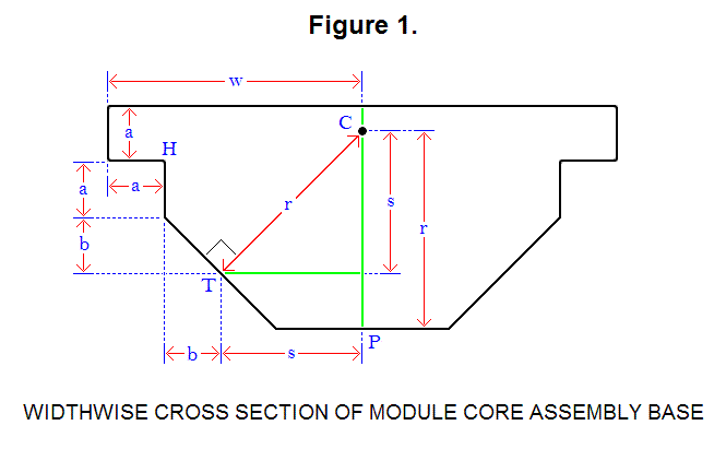
Six assemblies, and an optional power cube, form a module; each assembly is made up of several distinct components: a telescoping leg, one base that connects directly to the telescoping leg (the connecting plate), a module core base, and an intermediate component that connects the telescoping leg to the module core base. To maximize the space for the intermediate component of the assembly that connects the telescoping leg to the assembly’s module core connector base, there are optimal ratios for the lengths of the sides of the part of the assembly that connects to 4 other assemblies and the power cell (the module core assembly base), to form a module, and they can be calculated. Figure 1, below, is a diagram that shows a widthwise cross section of this component of the assembly.

Optimization is accomplished by setting the length of line segment CP to line segment CT and line segment CH, which are all equal to length r. For this diagram, the following equations are derived or set:

√2s = r                                                         (Equation 1)
w = a + b + s     →     w – a = b + s            (Equation 2)
s + a/2 = b + 2a     →      s = b + 3a/2      (Equation 3)
CP = CT = CH = r                                        (Equation 4)
(a/2)2 + (b + s)2 = r2                                  (Equation 5)

he ratios can be boiled down to a specific ratio k between 2 lengths, a and w (a ∝ w → ka = w); to solve for the constant of proportionality k, solve for a and w:

Plug equation 3 into equation 2:

w – a = 2b + 3a/2     →     b = w/2 – 5a/4      (Equation 6)

Plug equation 3 into equation 1:

√2(b + 3a/2) = r      (Equation 7)

Plug equation 2 into equation 5:

(a/2)2 + (w – a)2 = r2      (Equation 8)

Plug equation 7 into equation 8:

(a/2)2 + (w – a)2 = 2(b + 3a/2)2      (Equation 9)

Plug equation 6 into equation 9:

(a/2)2 + (w – a)2 = 2((w/2 – 5a/4) + 3a/2)2 → 4w2 – 20aw + 9a2 = 0      (Equation 10)

Setting a = 1 and solving for w in equation 10:

w = (5 +/- 4)/2 = 0.5 and 4.5

Since w > a, w = 4.5; so, the ratio k between a and w is:

k = 4.5

Solving for b, r, and s (for a = 1):

b = (4.5)/2 – 5(1)/4 = 2.25 – 1.25 = 1
r = √2((1) + 3(1)/2) = √2∙2.5 ≈ 3.536
s = (1) + 3(1)/2 = 2.5

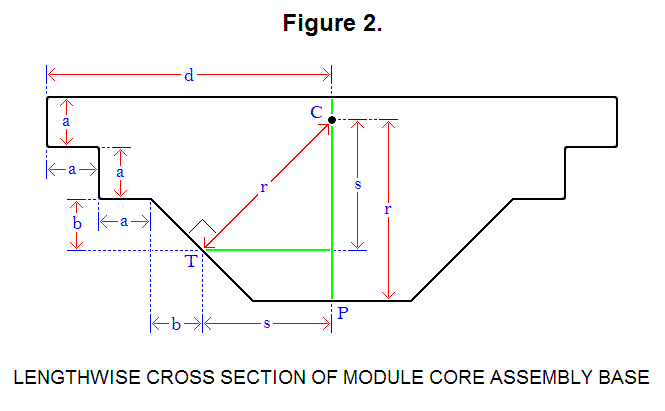
Figure 2, below, is a diagram that shows a lengthwise cross section of this component of the assembly.

For this diagram, the following equations is derived:

d = 2a + b + s     (Equation 11)

Solving for d (for a = 1):

d = 2(1) + (1) + 2.5 = 5.5

Ratio of each length in terms of a:

b = a                         (Formula #1)
w = 4.5∙a                         (Formula #2)
d = 5.5∙a                         (Formula #3)
r ≈ 3.536∙a                         (Formula #4)
s = 2.5∙a                         (Formula #5)

The Cantilever and a Benefit of Having a Large-Radius Connecting Plate

THE CANTILEVER AND A BENEFIT OF HAVING A LARGE-RADIUS CONNECTING PLATE

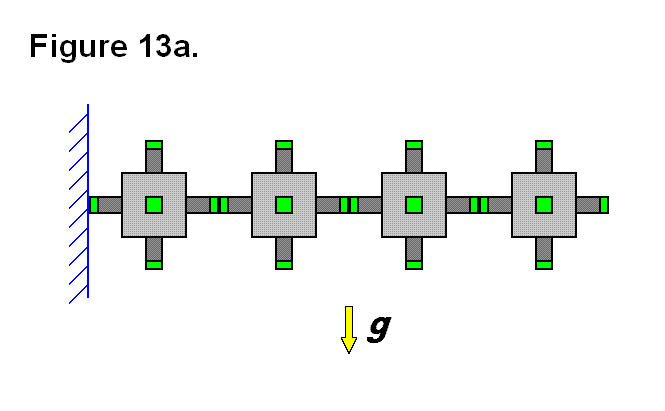
In some applications it is necessary to be able to form cantilevers with the modules; to form a cantilever requires several modules to be connected in series horizontally. Figure 13a shows a row of four modules with small connecting ends, in green, joined together in a row and mounted on the left side to a wall, in blue; gravity g, represented as a yellow arrow, is a force pulling downward. The connection between the left module and the other three modules is limited in strength between the connecting ends on either side, and is under tremendous stress as the axis for a moment of force introduced by the three modules on the right and gravity; this limits the number of modules that can be joined horizontally before these connecting ends fail.

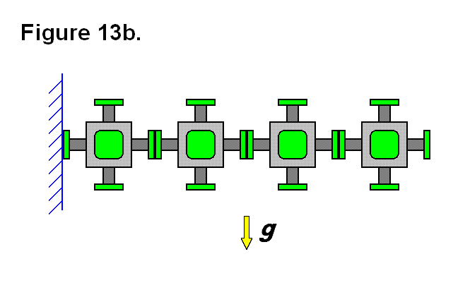
By simply increasing the radius of the connecting end from r = 1 unit to r = R units, the area of the connecting plate surface is increased by a ratio of R2 units (of area to 1 unit of area). Figure 13b shows the four modules, from Figure 13a, with larger radius connecting plates. The axis of the moment of force between the left module and the other three modules also moves closer to the top of the connecting plates and allows the area under that point between the connecting plates to help support the cantilevered row of modules. These features increase the limit of the number of modules that can be joined horizontally.

For the same reasons, the modules are limited in the length of the cantilever that they can produce by extending the legs that connect the modules together along the row; so a larger radius connecting plate also allows for longer rows of cantilevered modules. A feature that is provided by the actuated legs of the modules is the ability of the matrix to keep the cantilevered modules perfectly horizontal if necessary, rather than having the end of the cantilever droop downward.

Chain Articulation Benefit

CHAIN ARTICULATION BENEFIT

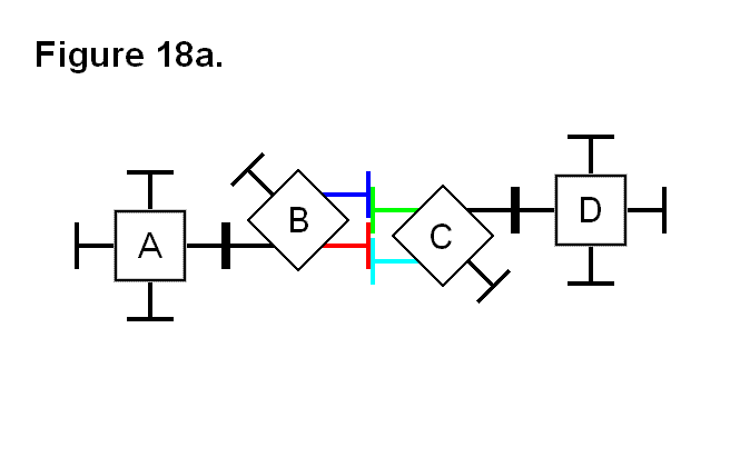
With the use of a method involving chained cells, it is unnecessary for any of the legs to be able to pivot more than 45°. Figure 18a shows a situation where cells A and B are joined to each other, and cells C and D are also joined to each other. Cells B and C are in contact with each other with the 2 pairs of legs from each cell shown in different colors. Since neither pair of connecting legs between cells are aligned, they cannot connect without pivoting the legs more than 45° in this position.

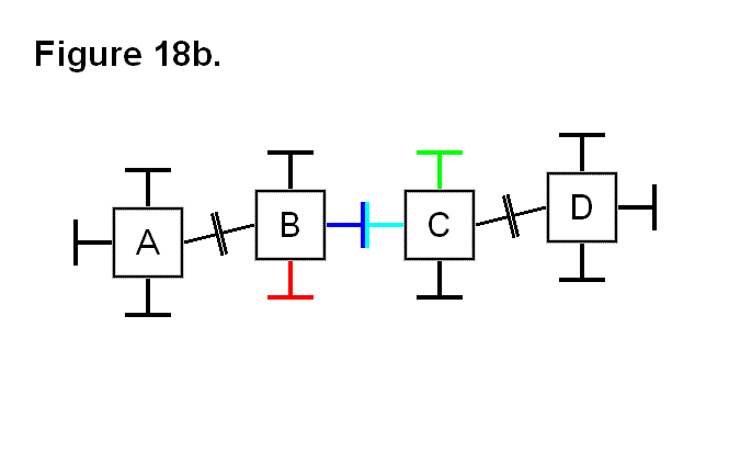
Without having to move from their positions, cells A and D can assist cells B and C with connecting together without the need for any of the the legs to be able to pivot more than 45°. Figure 18b shows how the cells can be arranged by pivoting the legs between the two pairs of cells to make this possible; the legs on the opposite sides of cells B and C are used to connect these cells together.