PROTOTYPES MADE FROM LEGOS (Page 3 of 3)
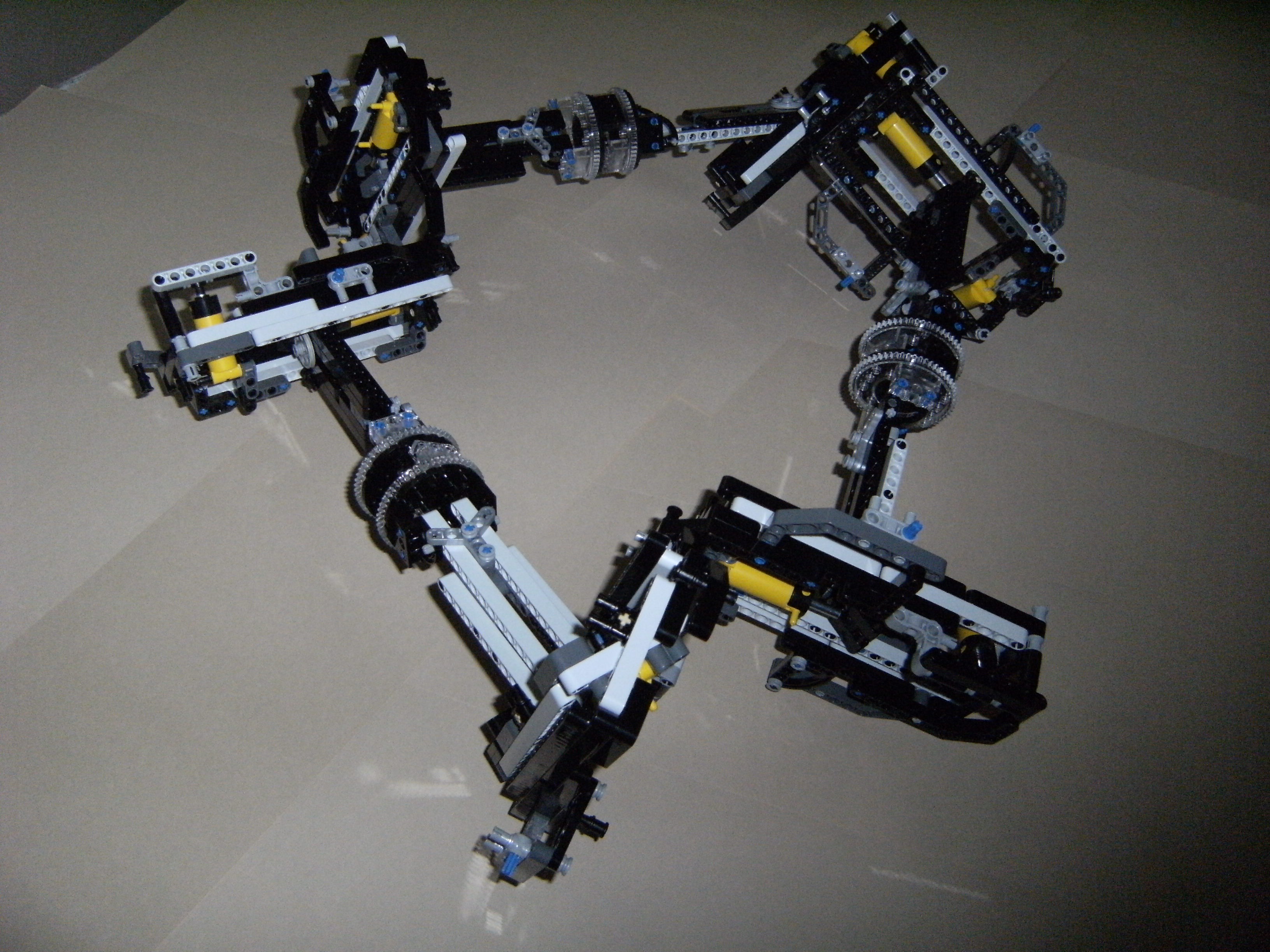
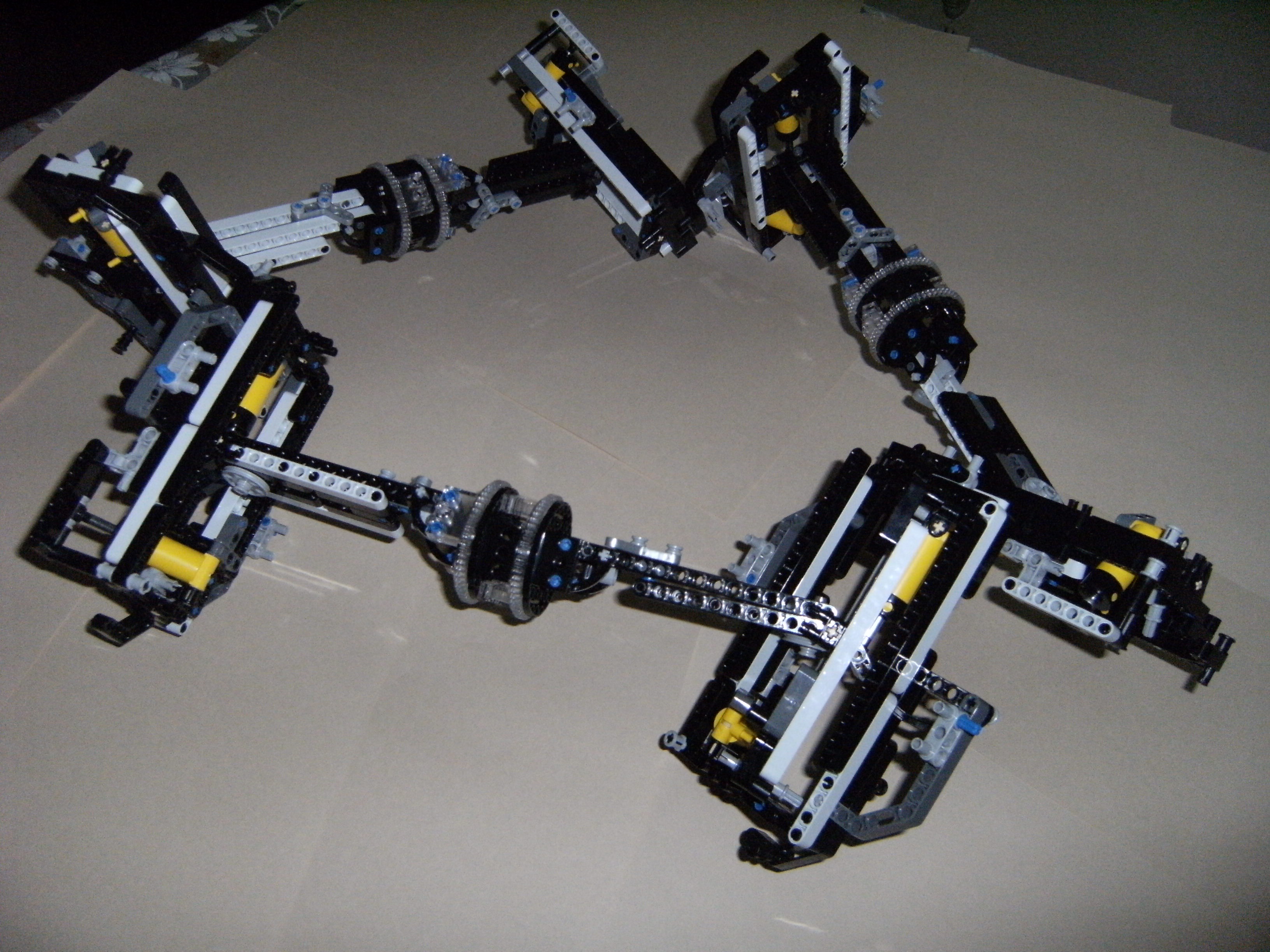
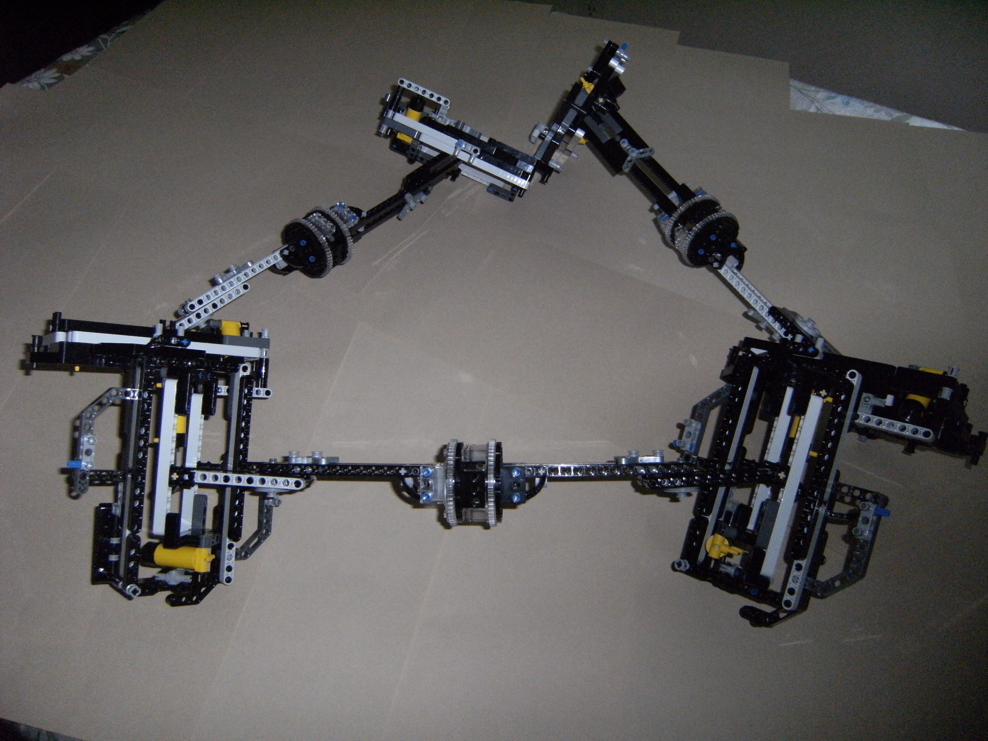
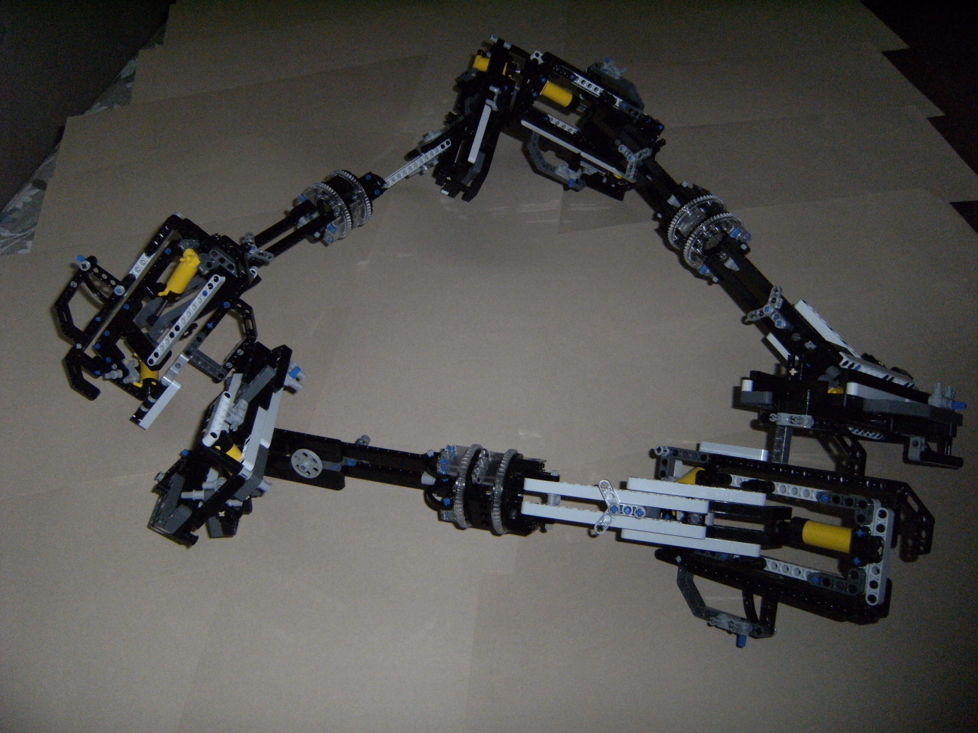
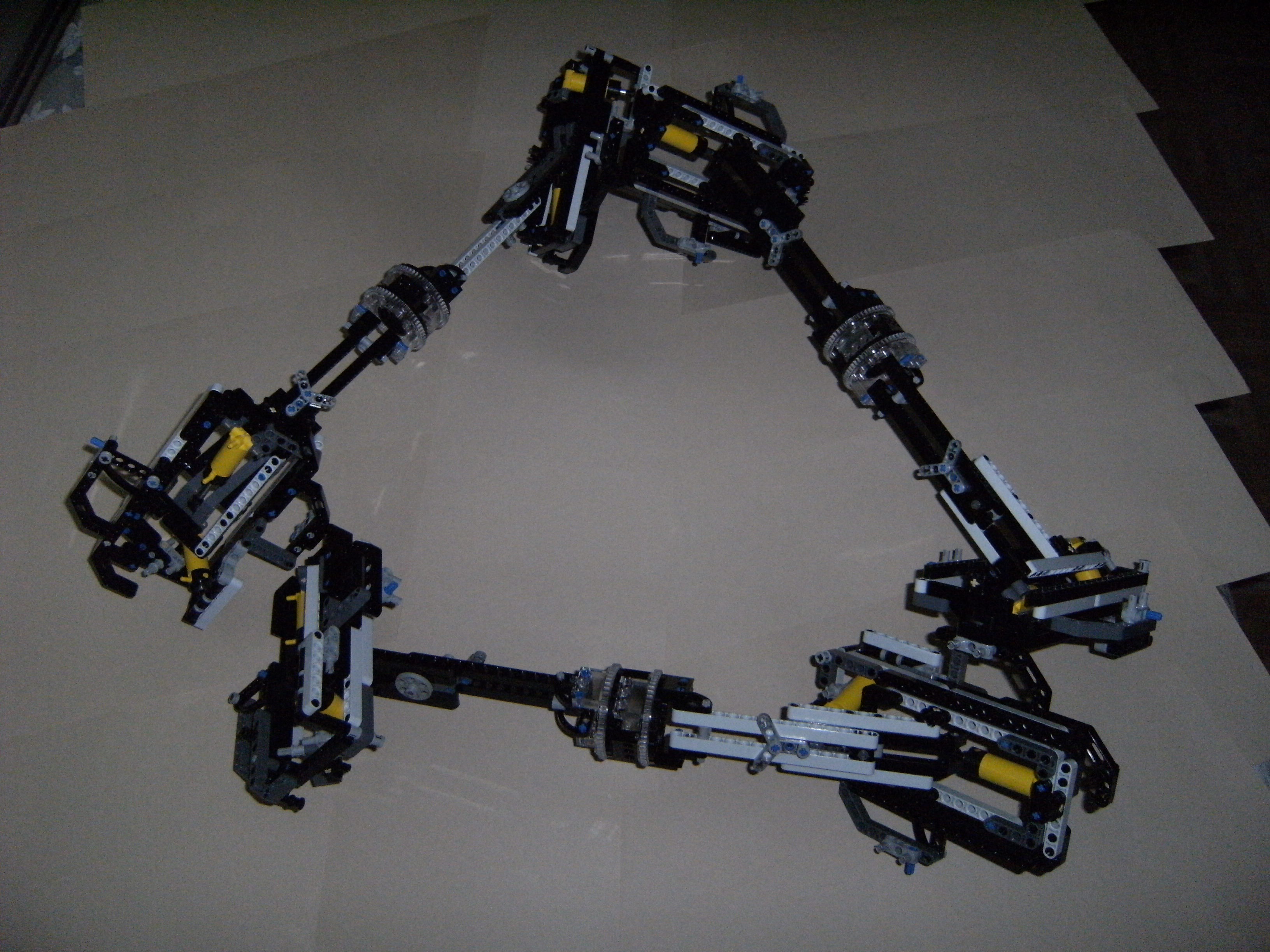
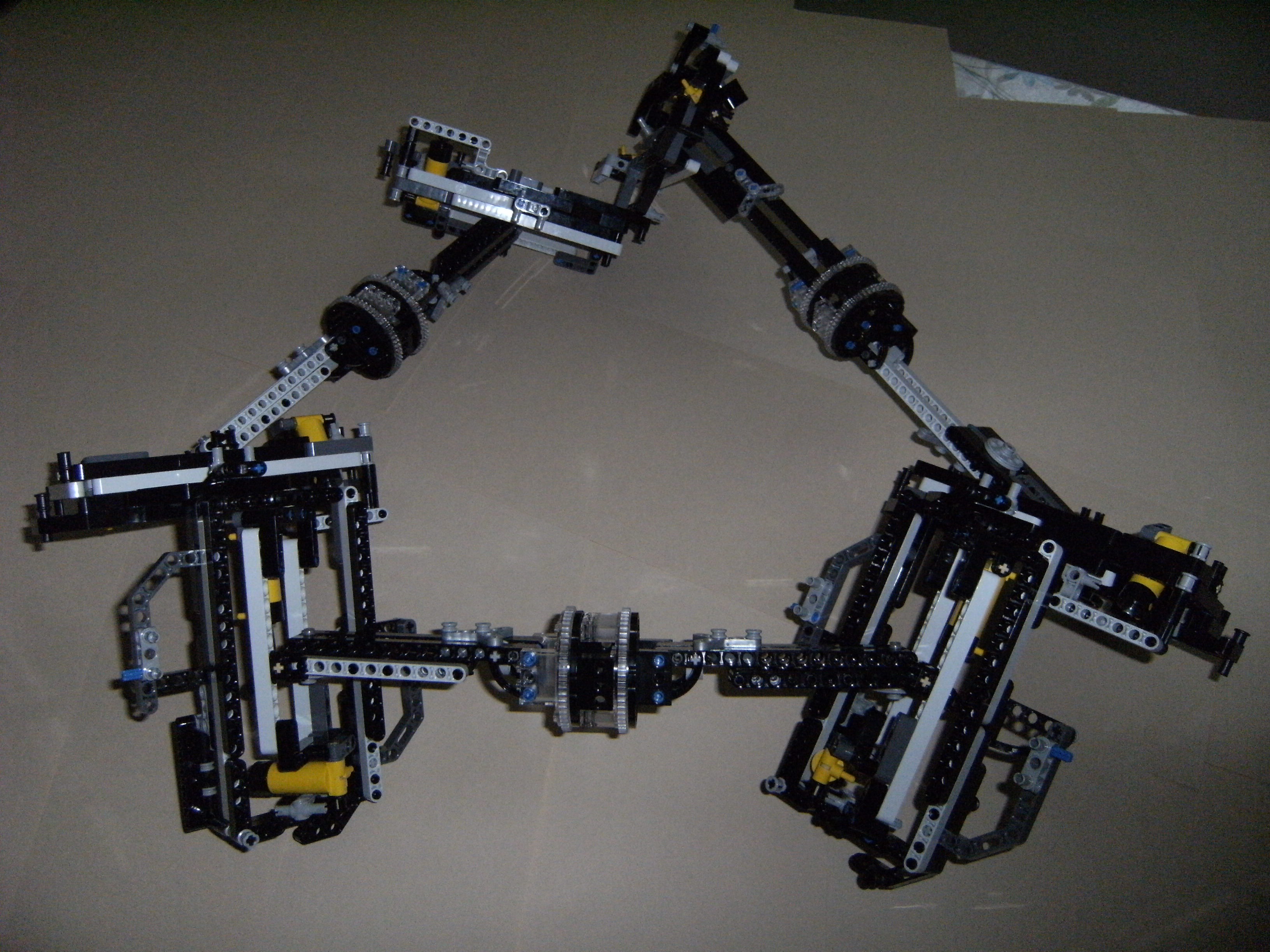
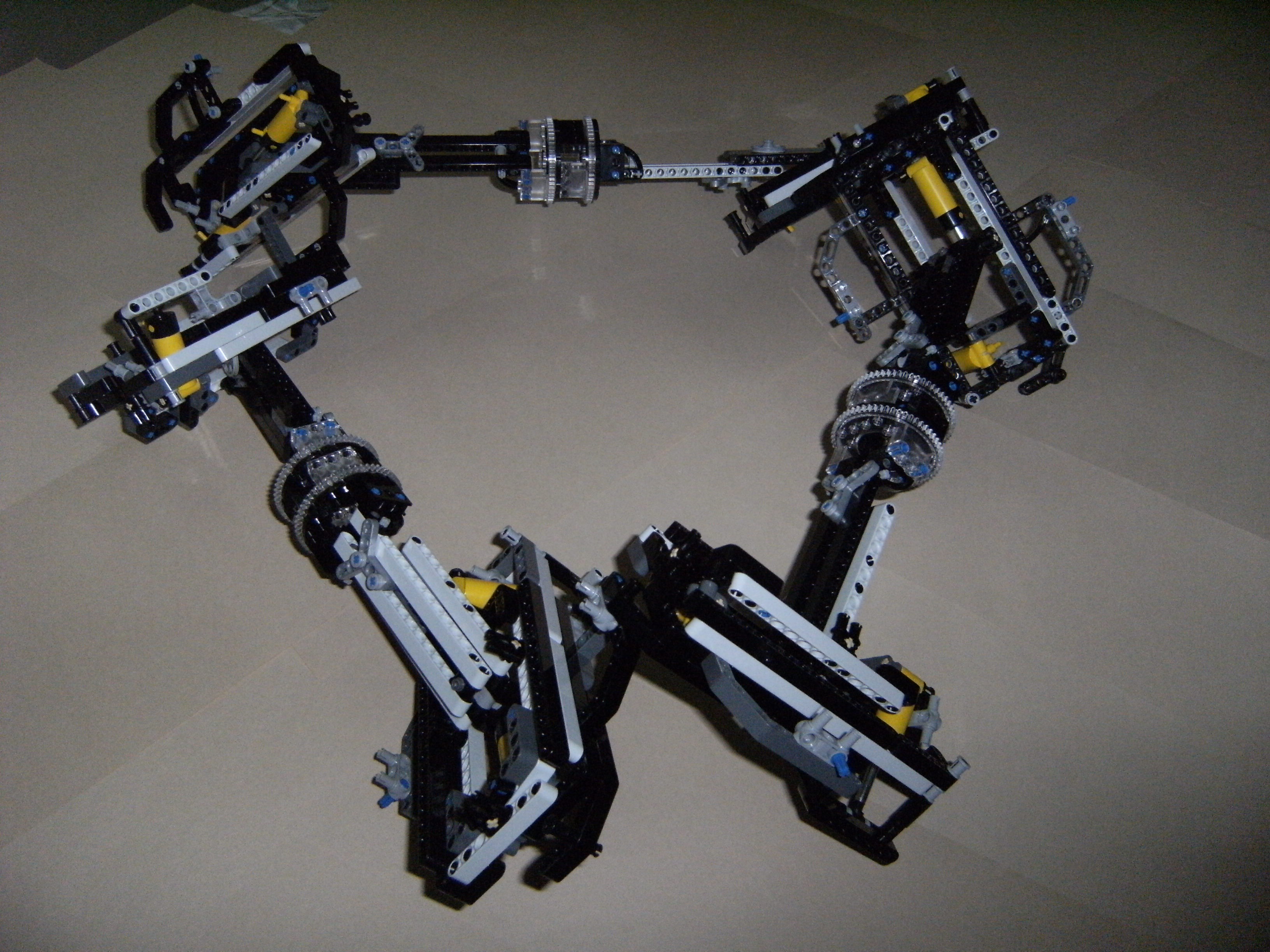
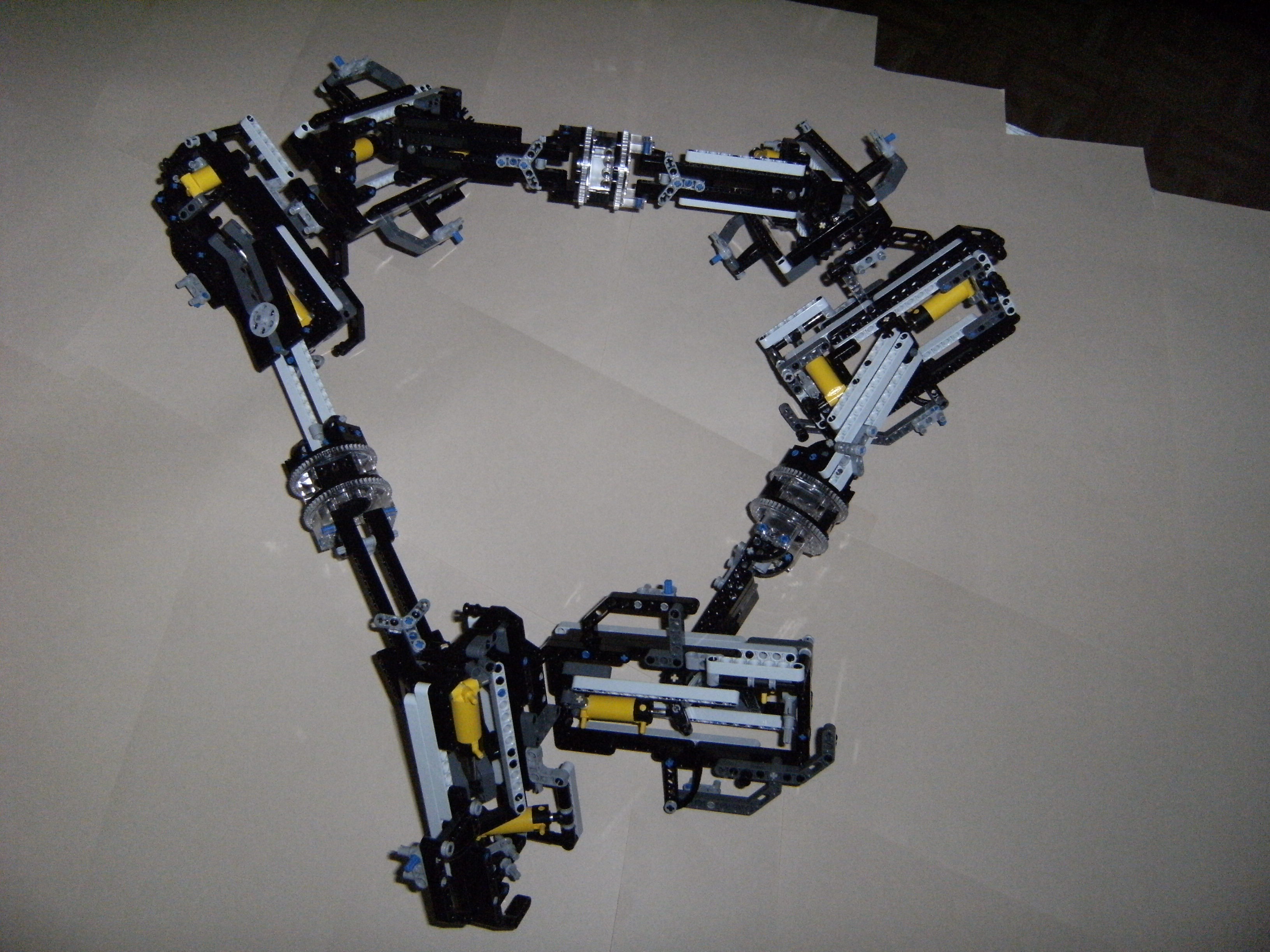
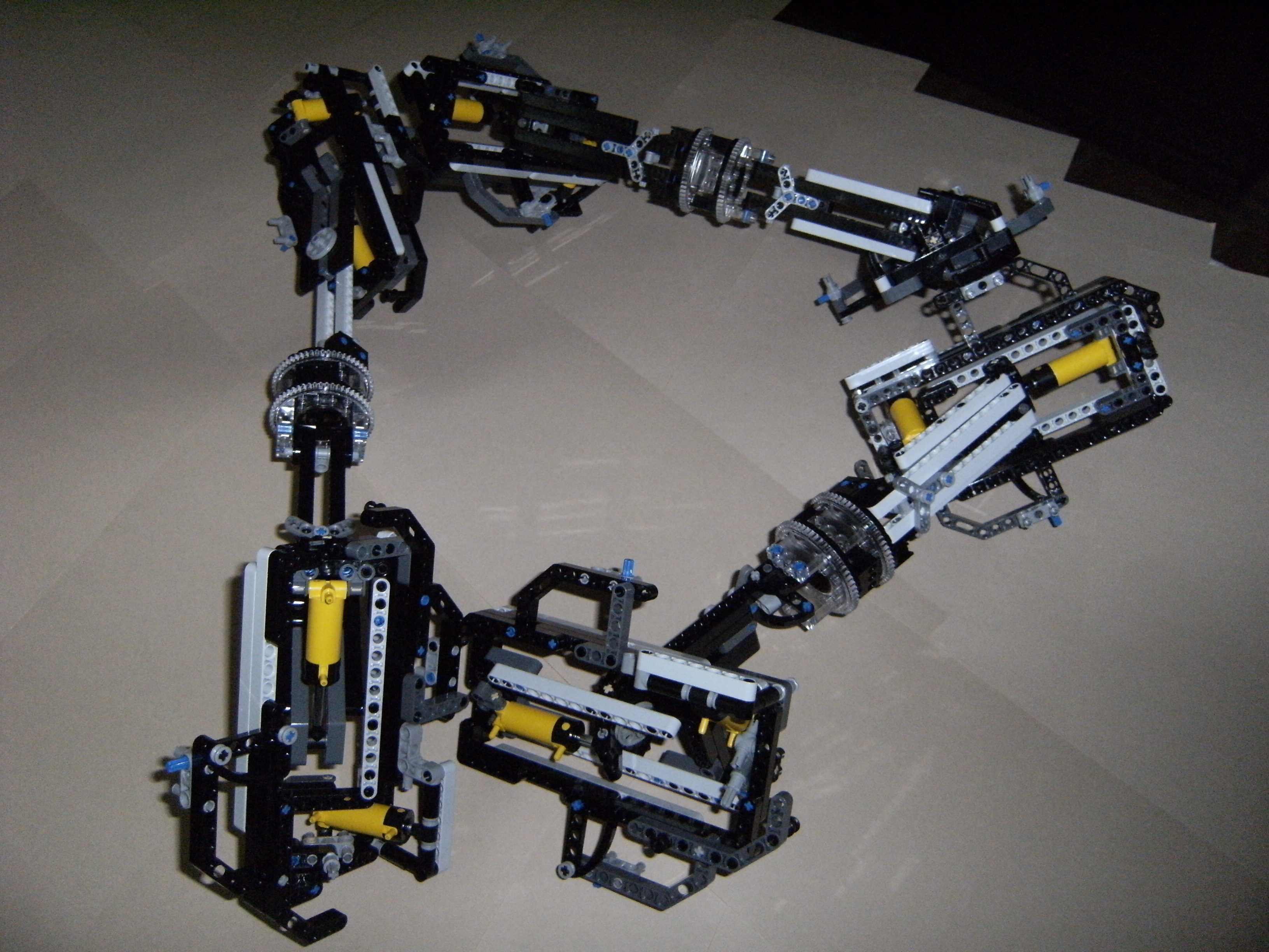
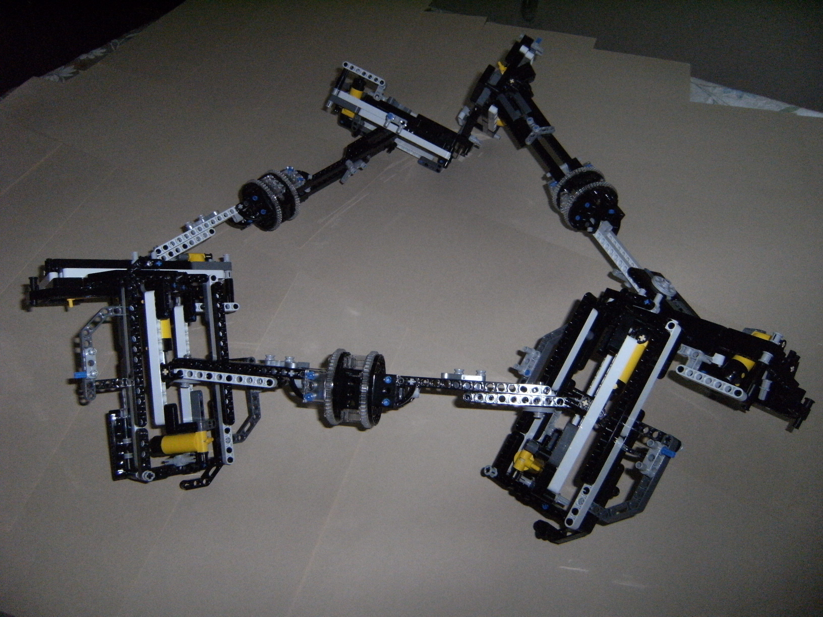
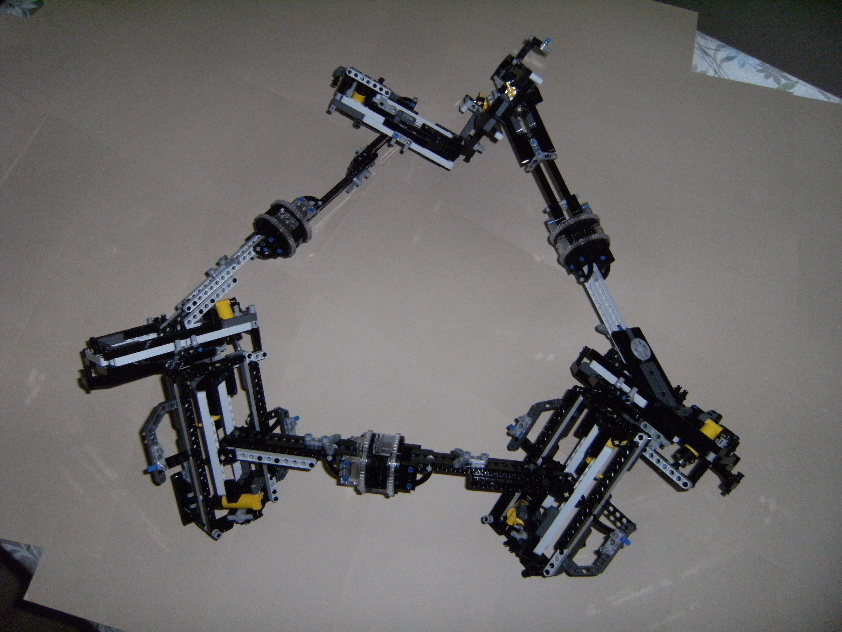
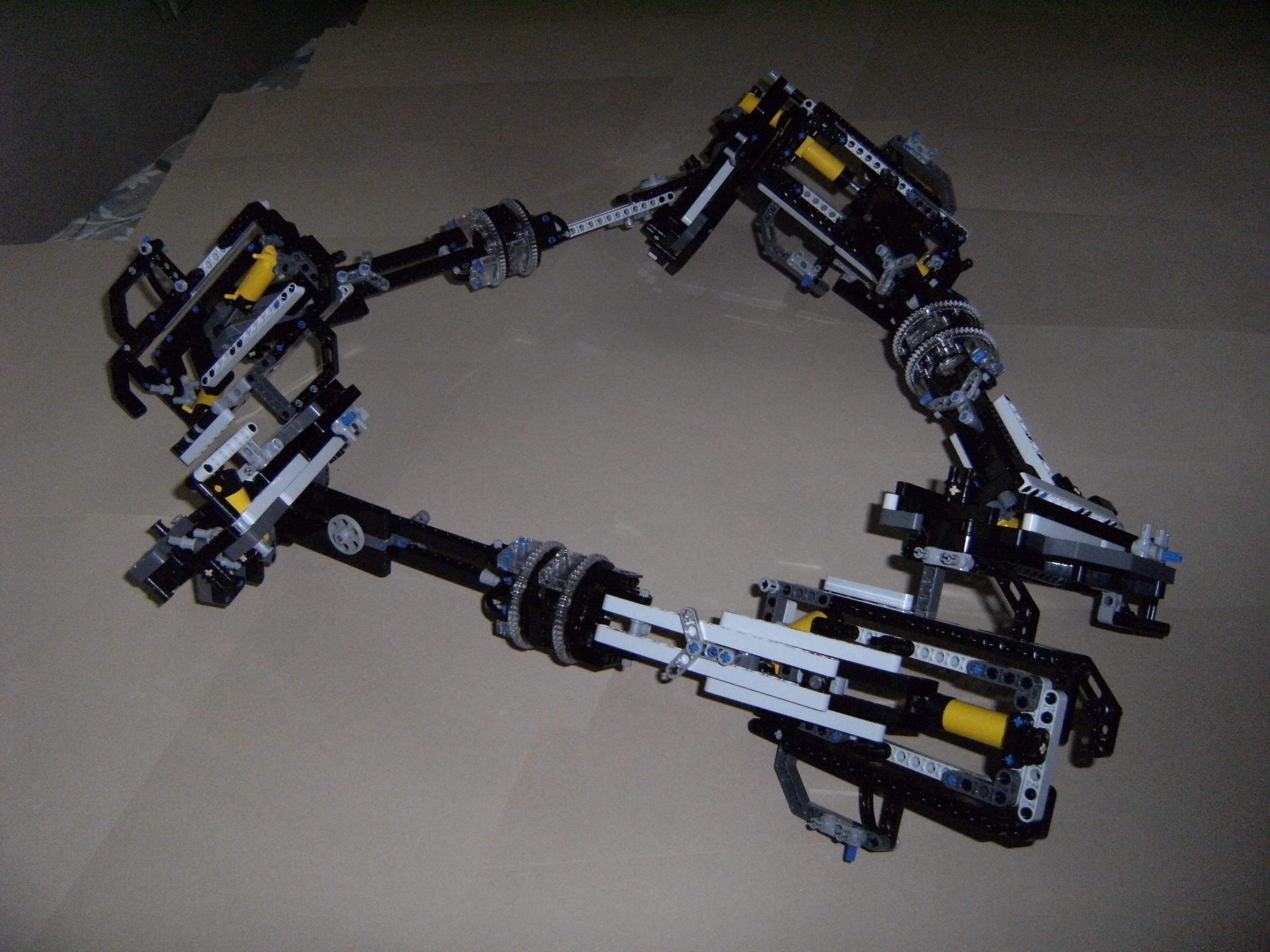
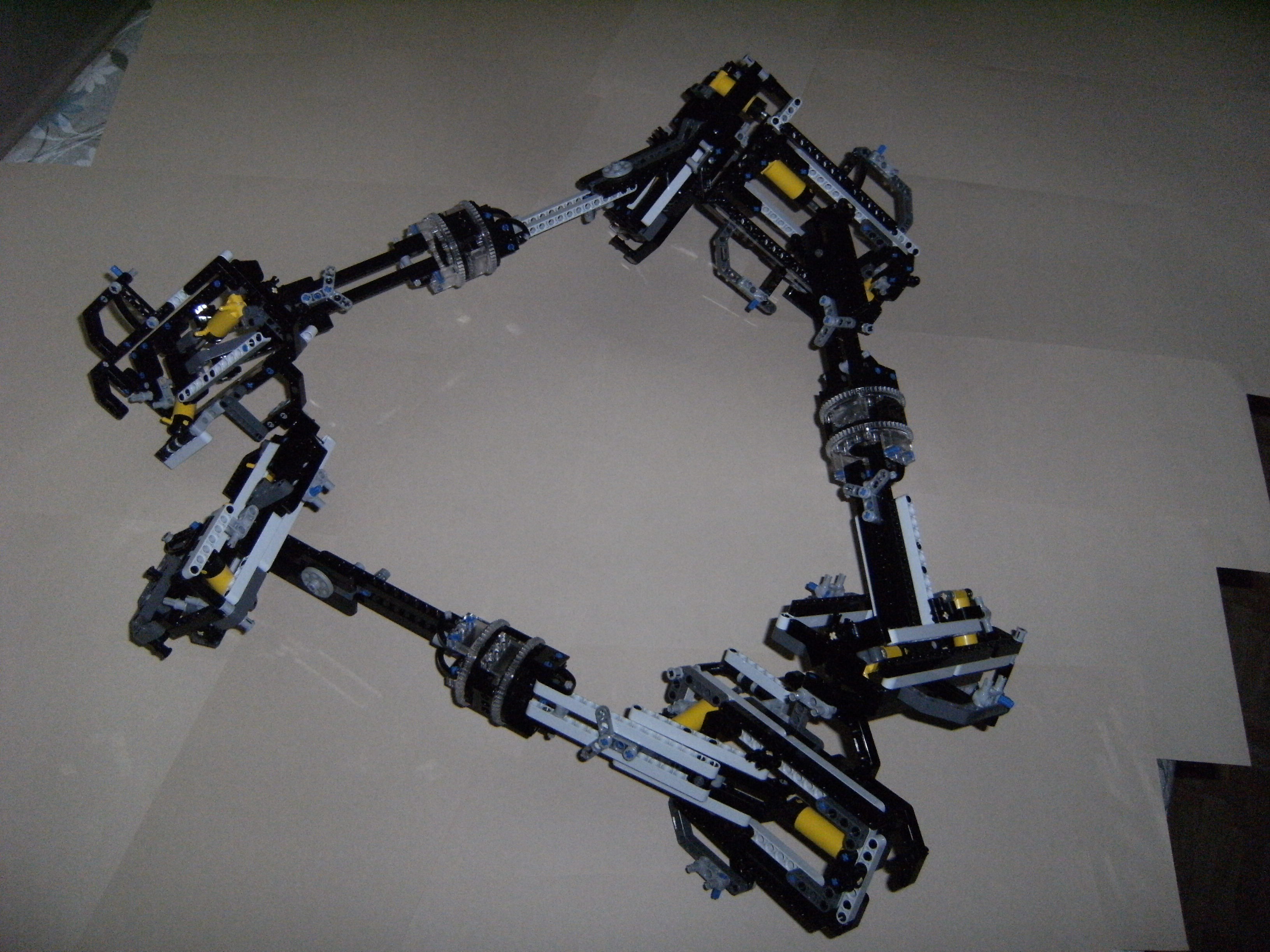
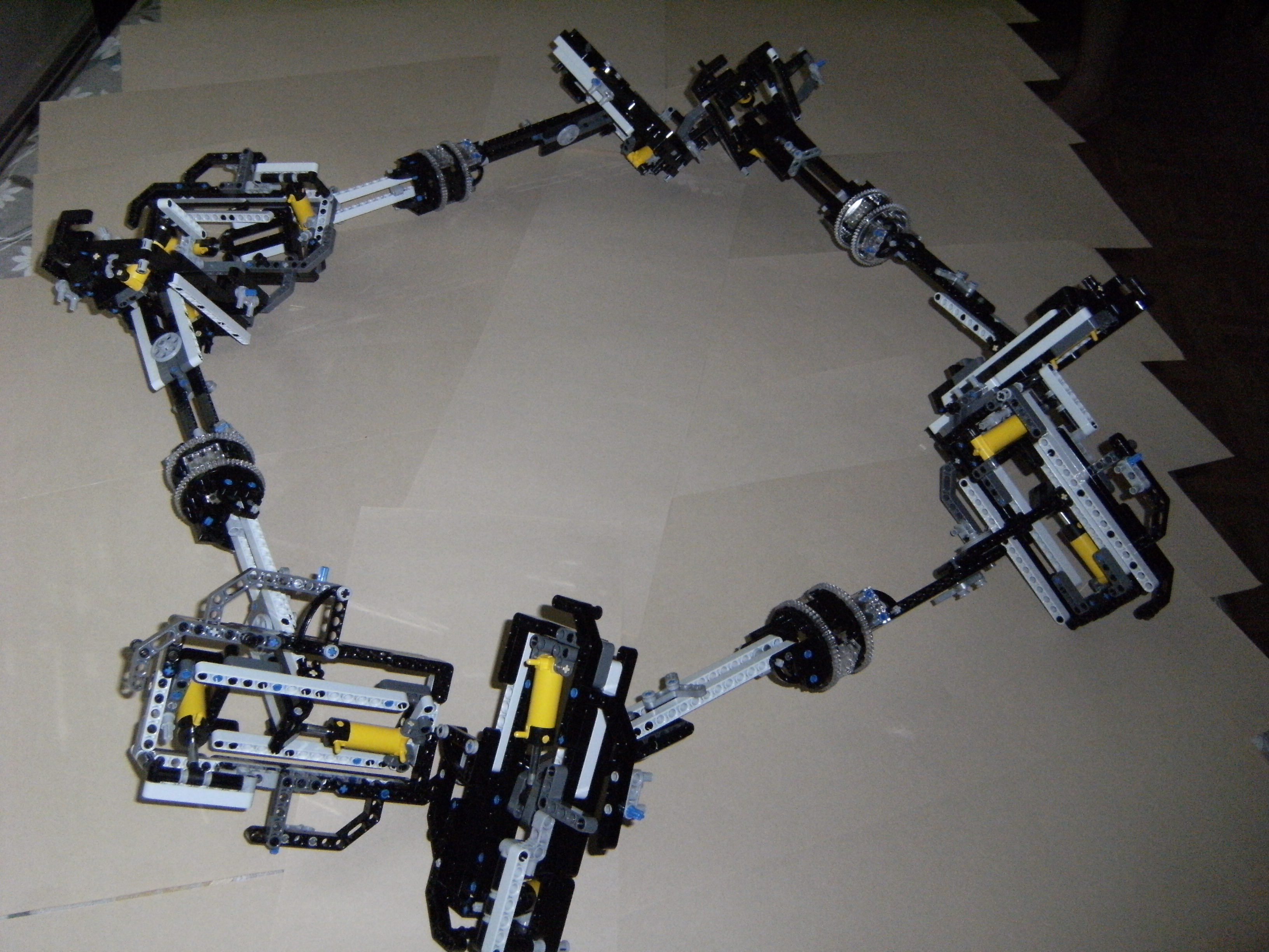
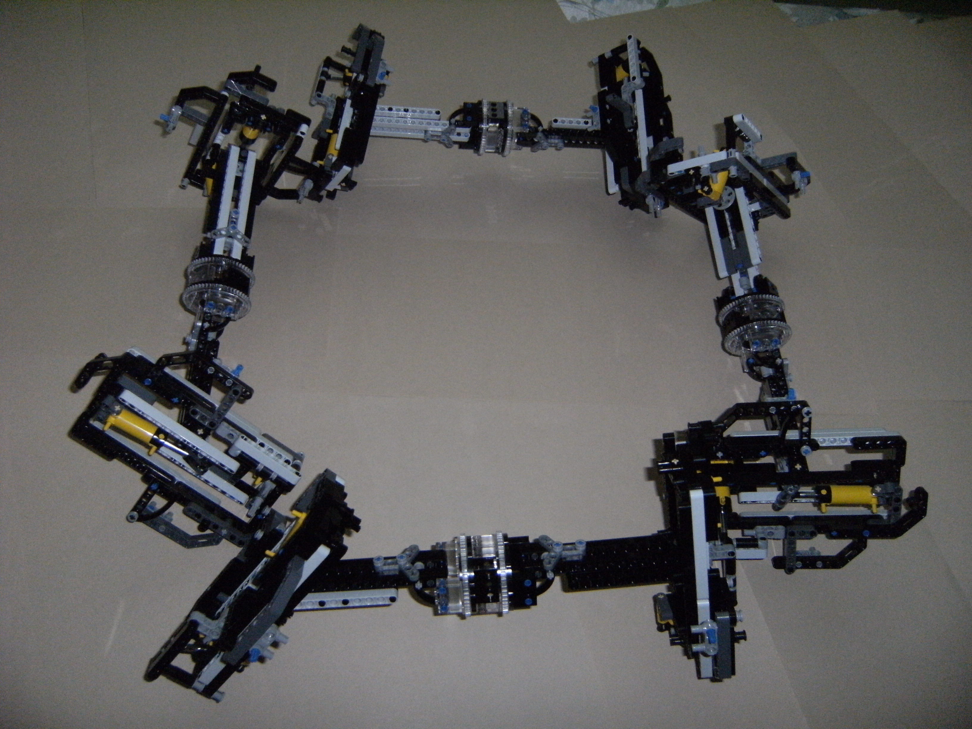
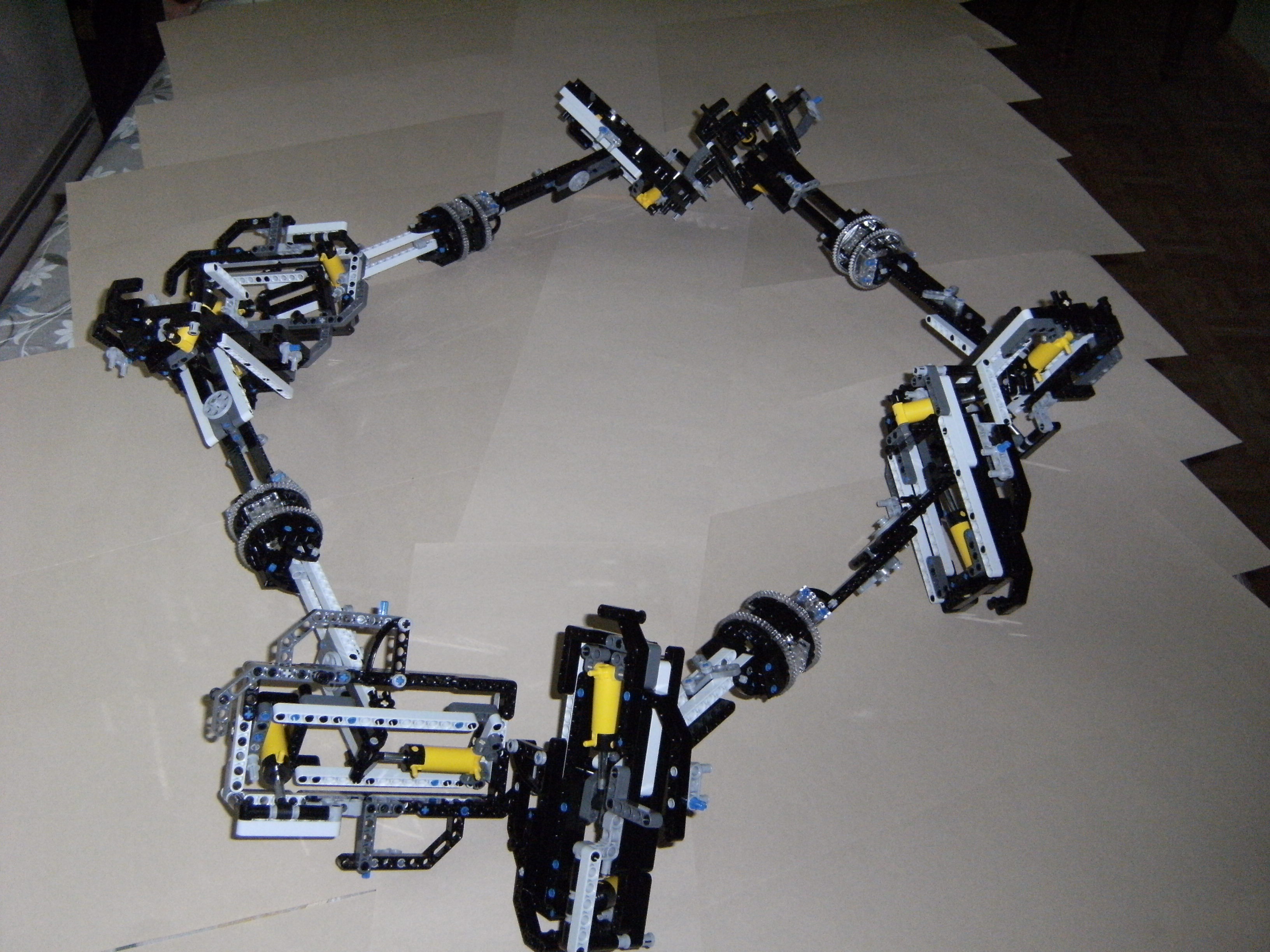
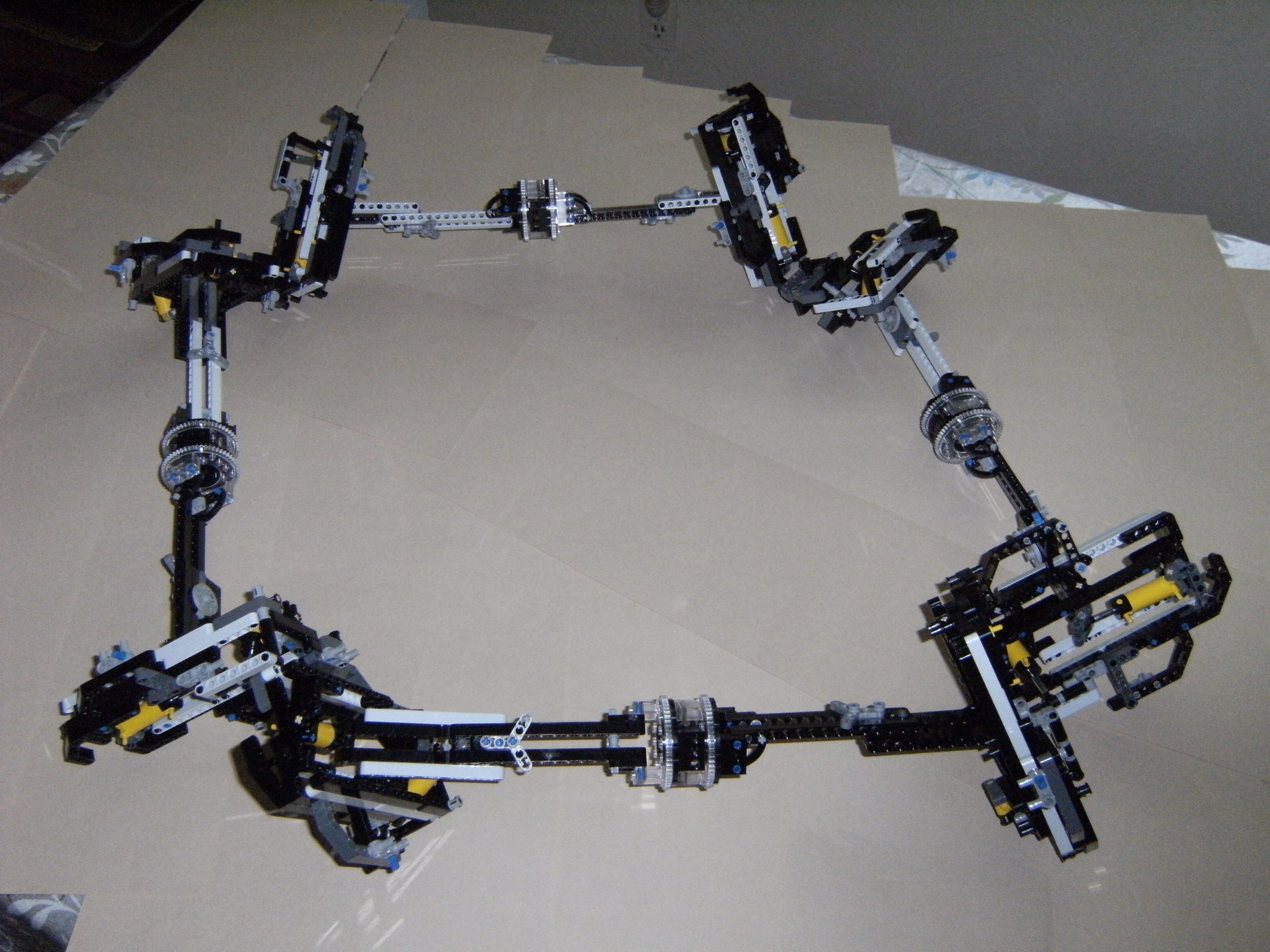
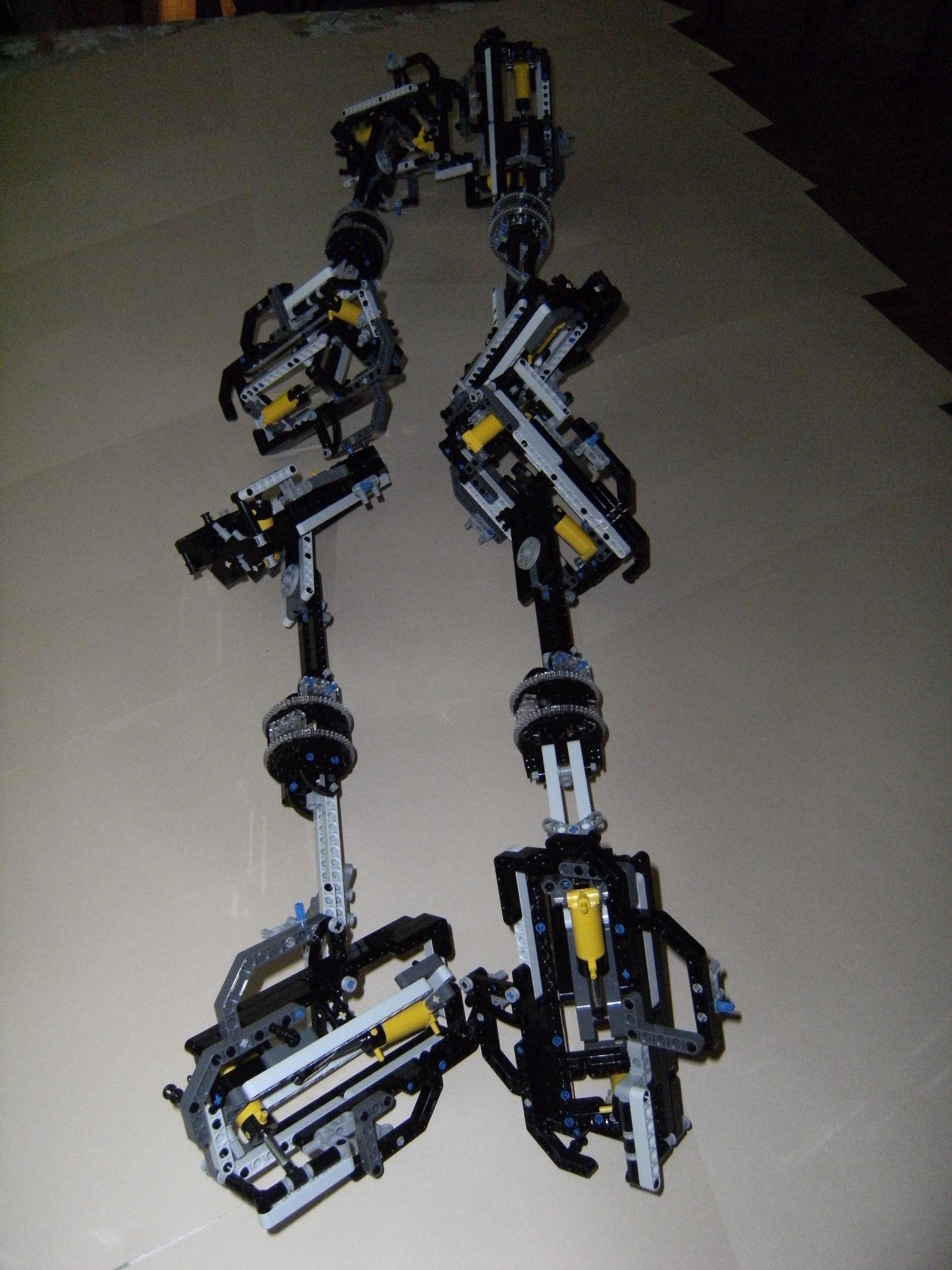
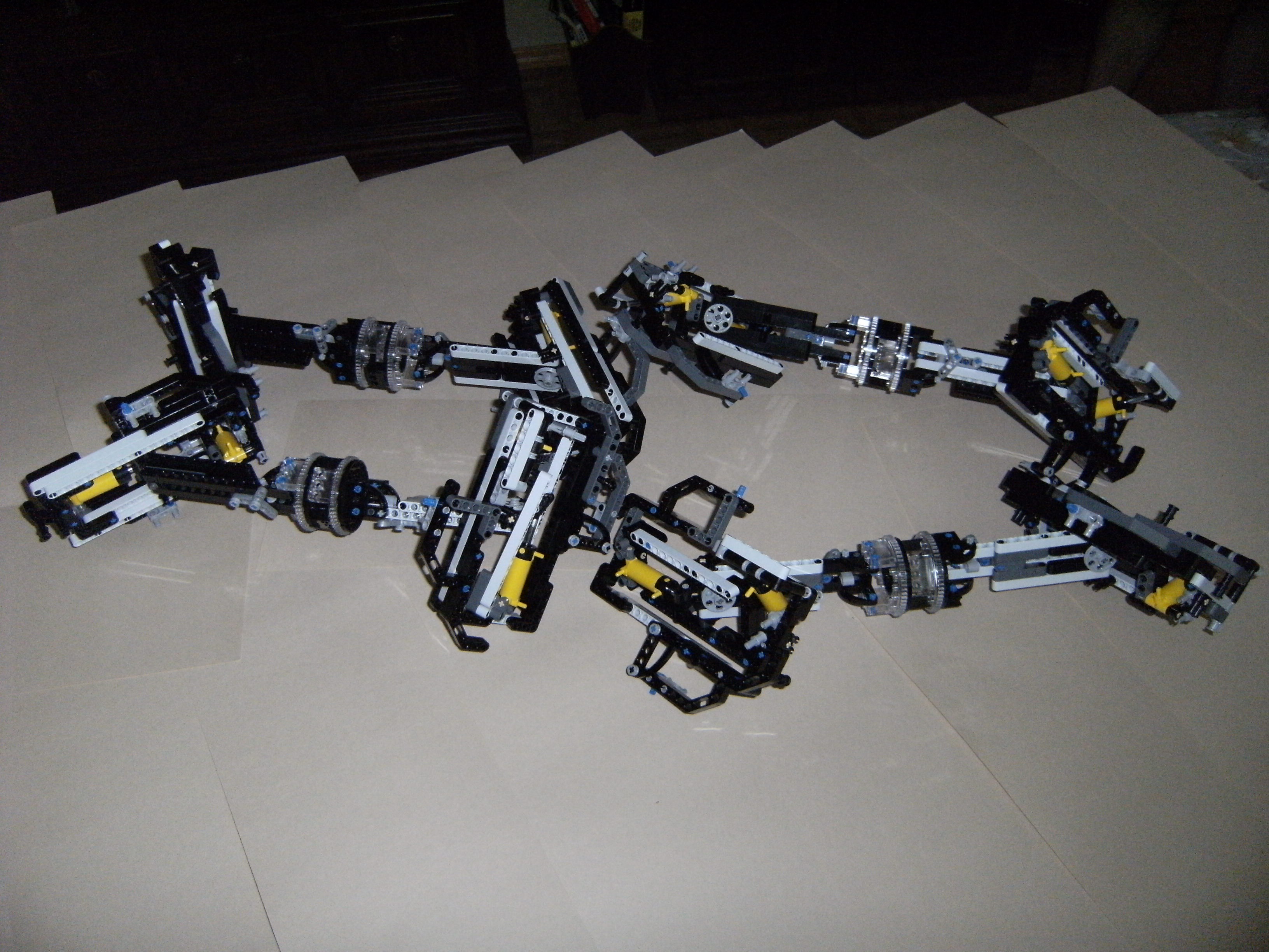
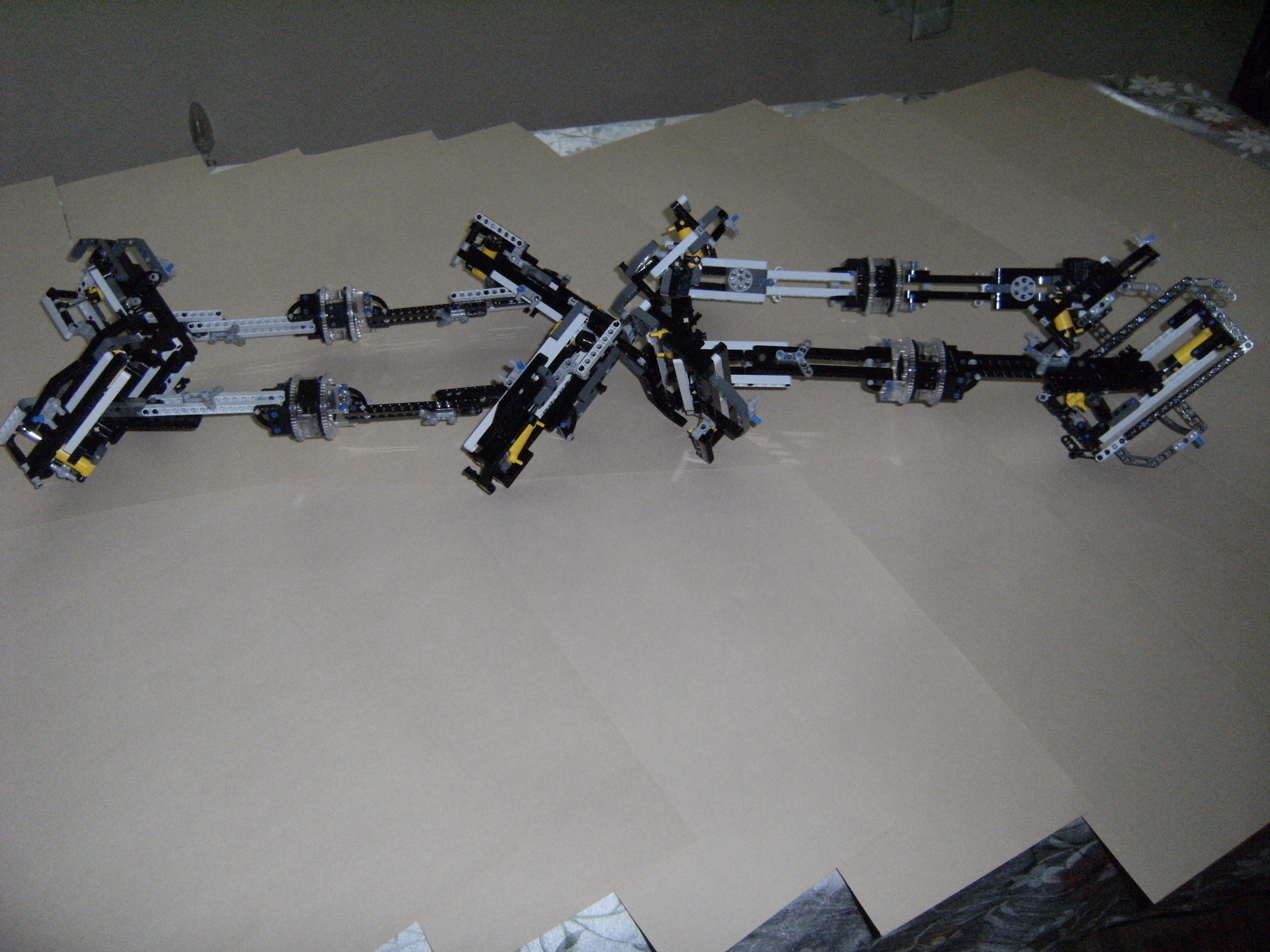
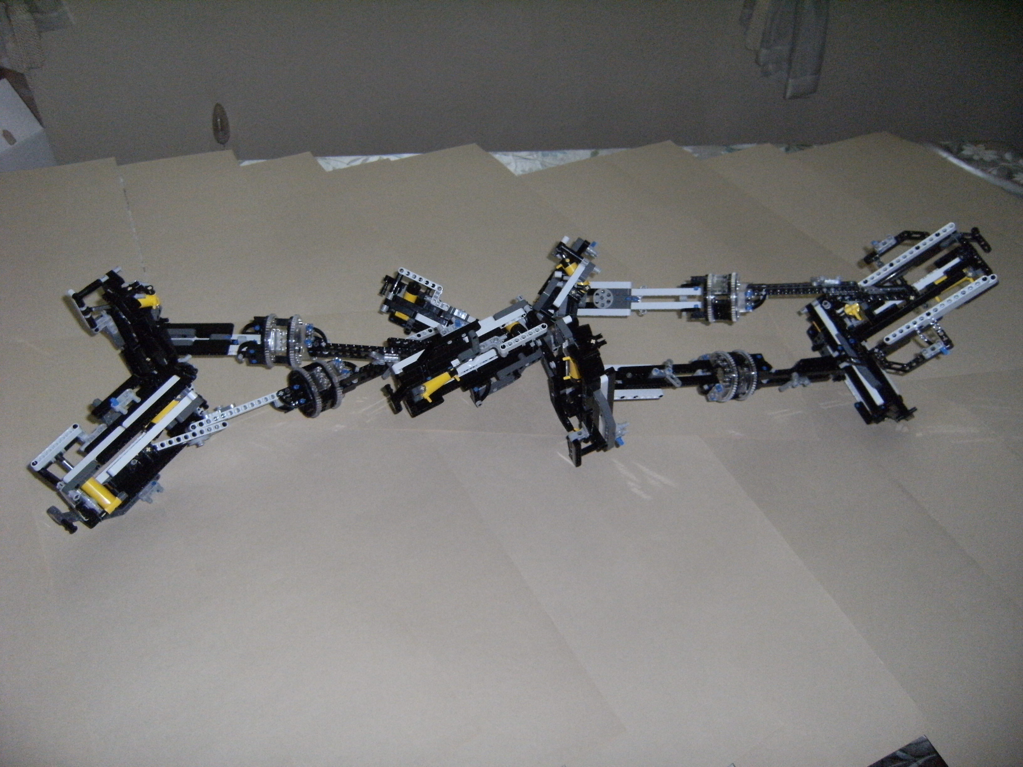
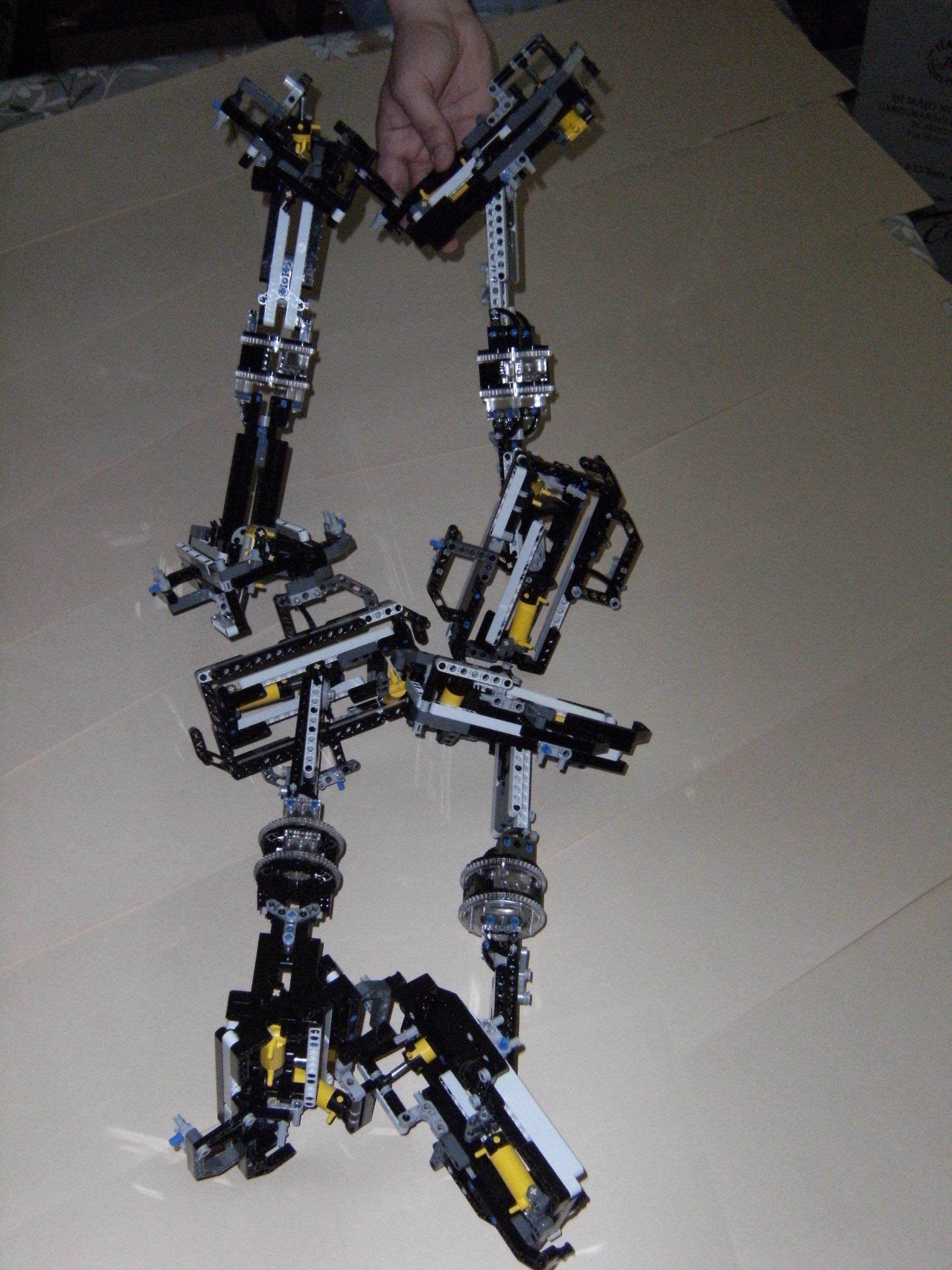
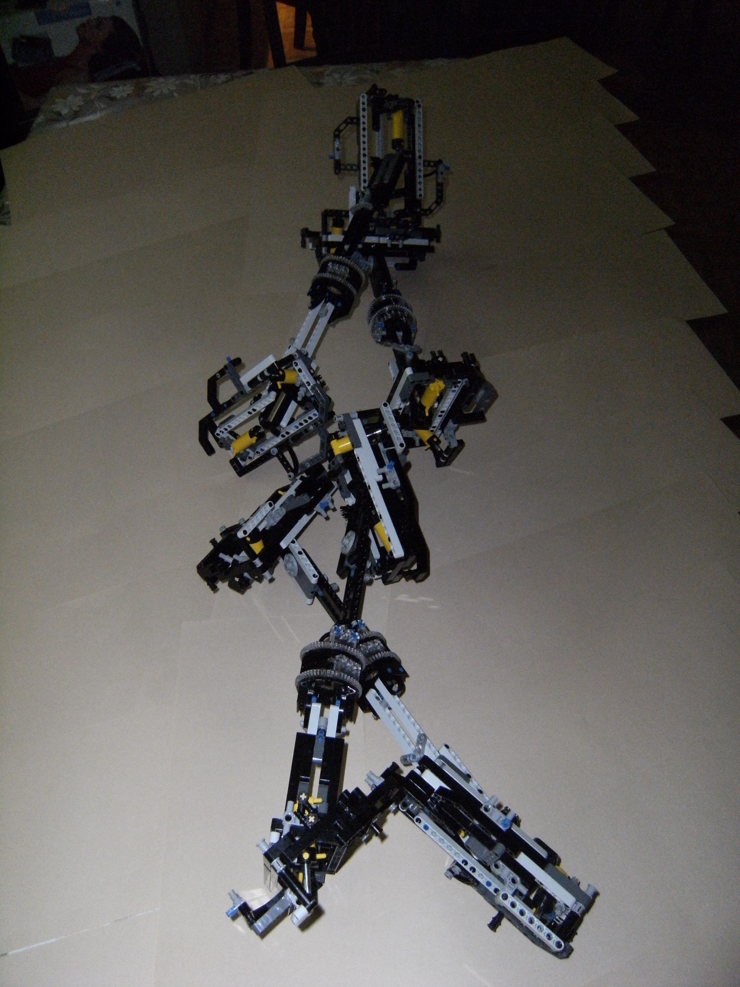
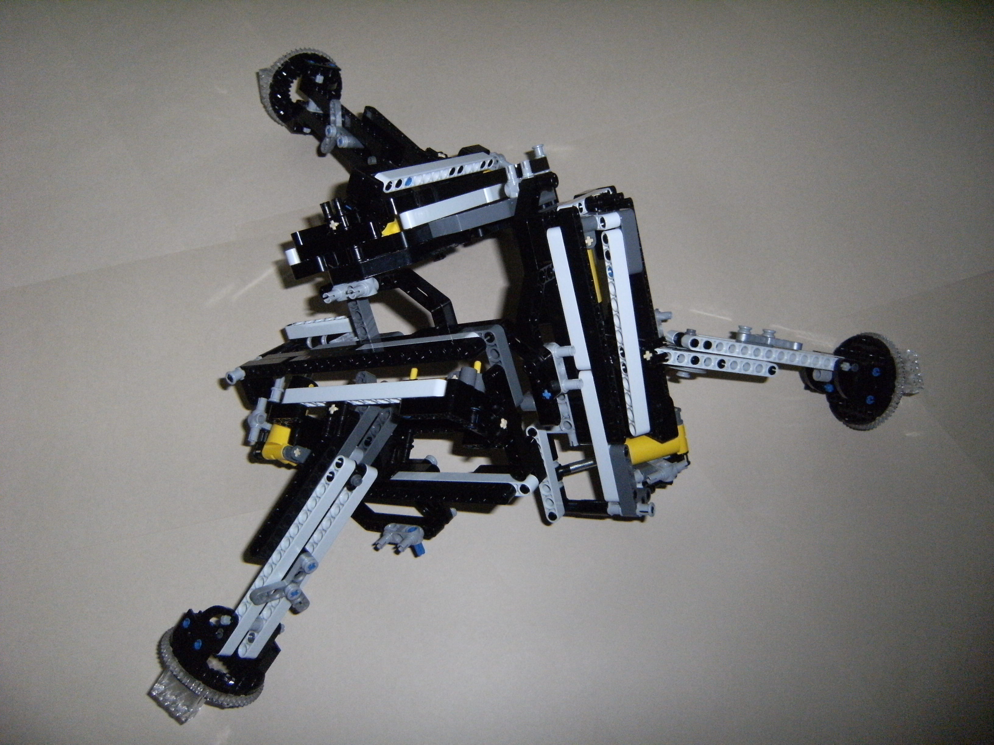
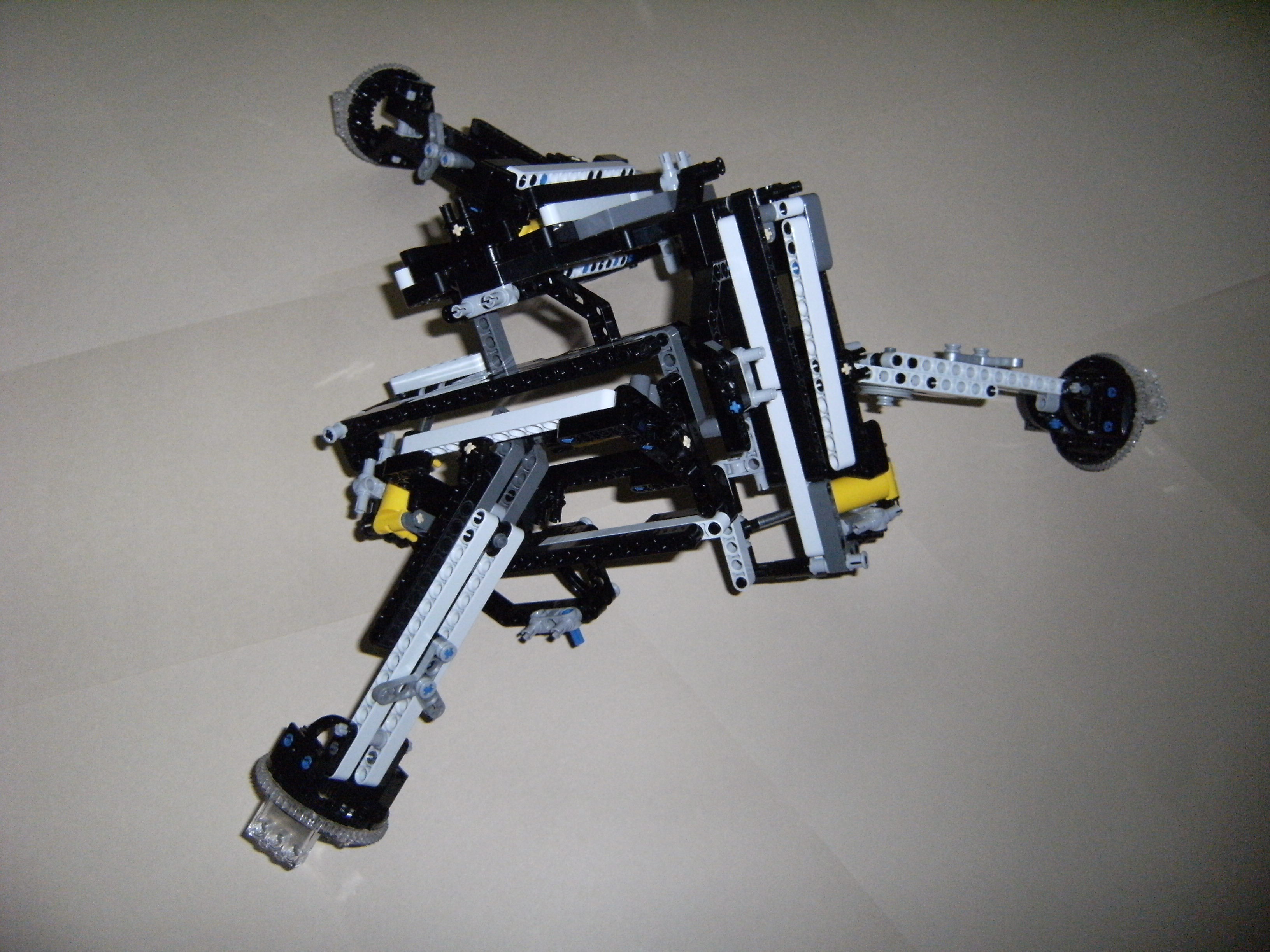
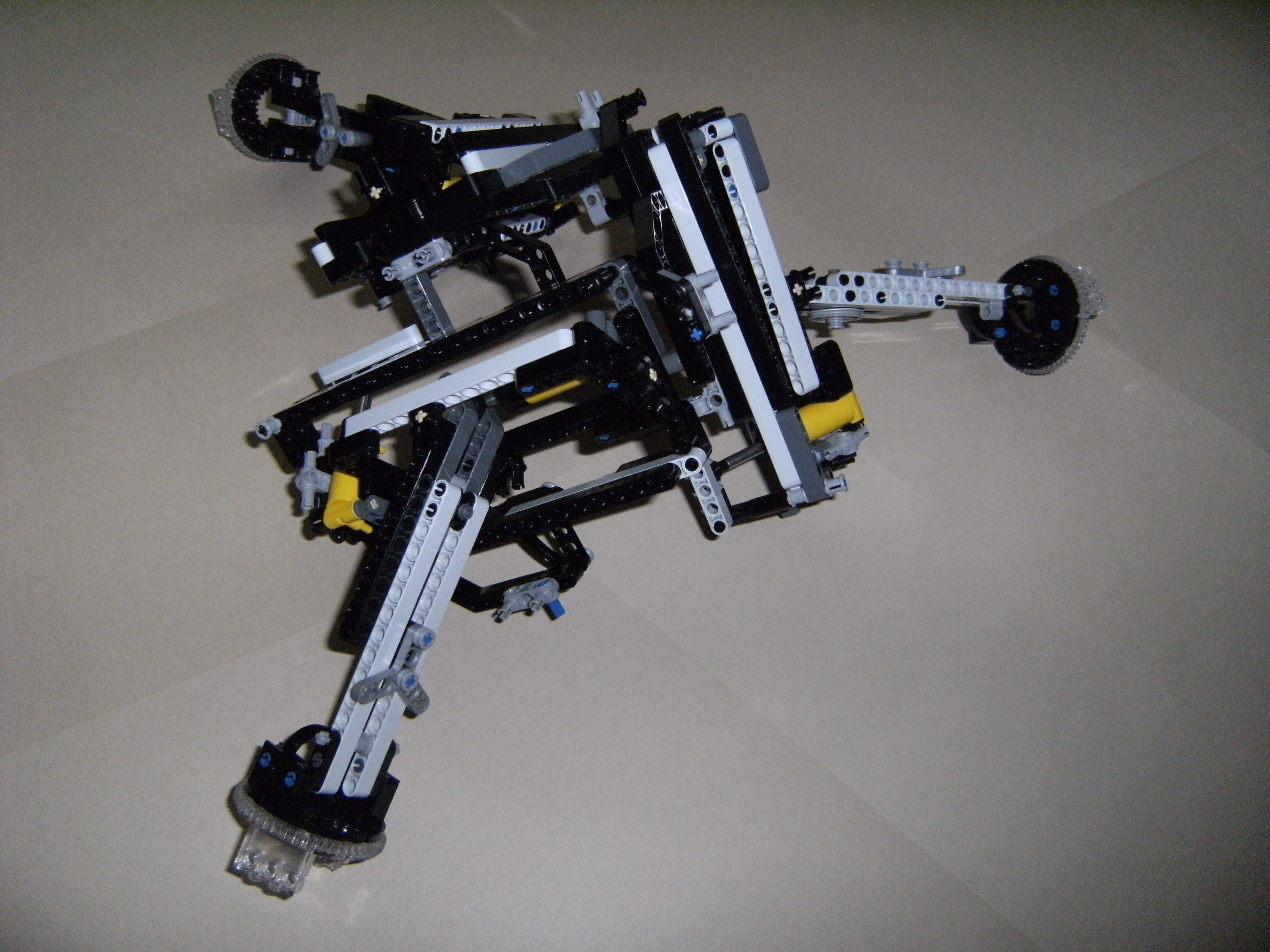
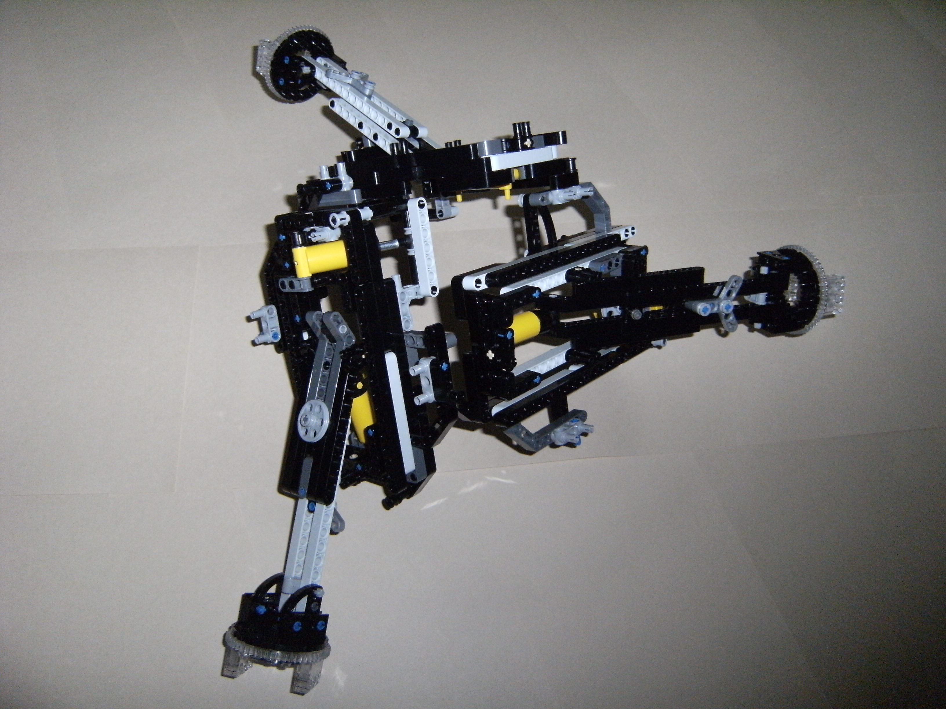
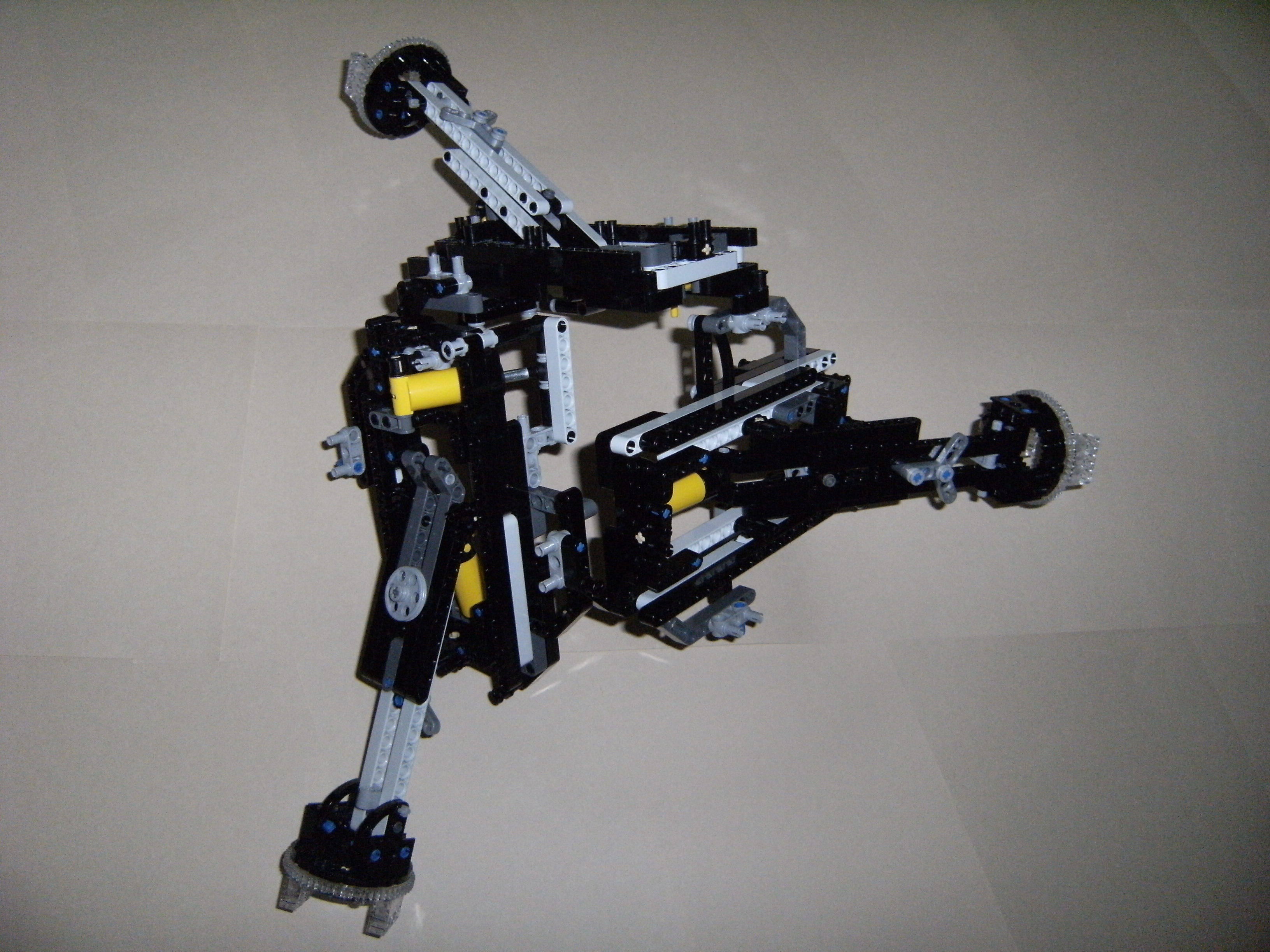
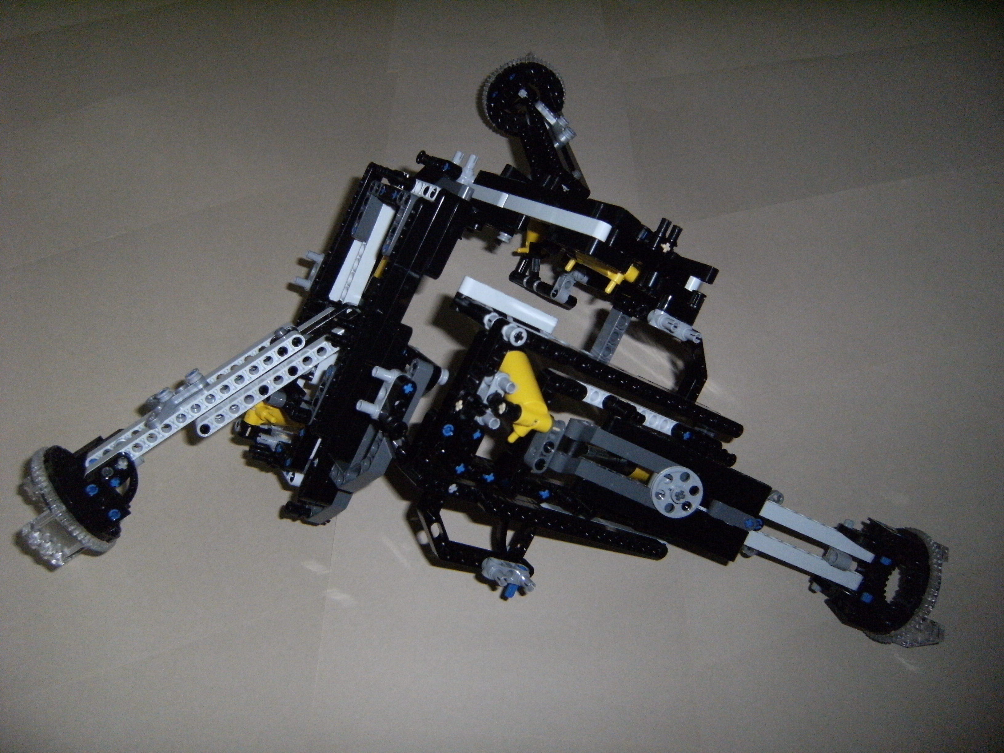
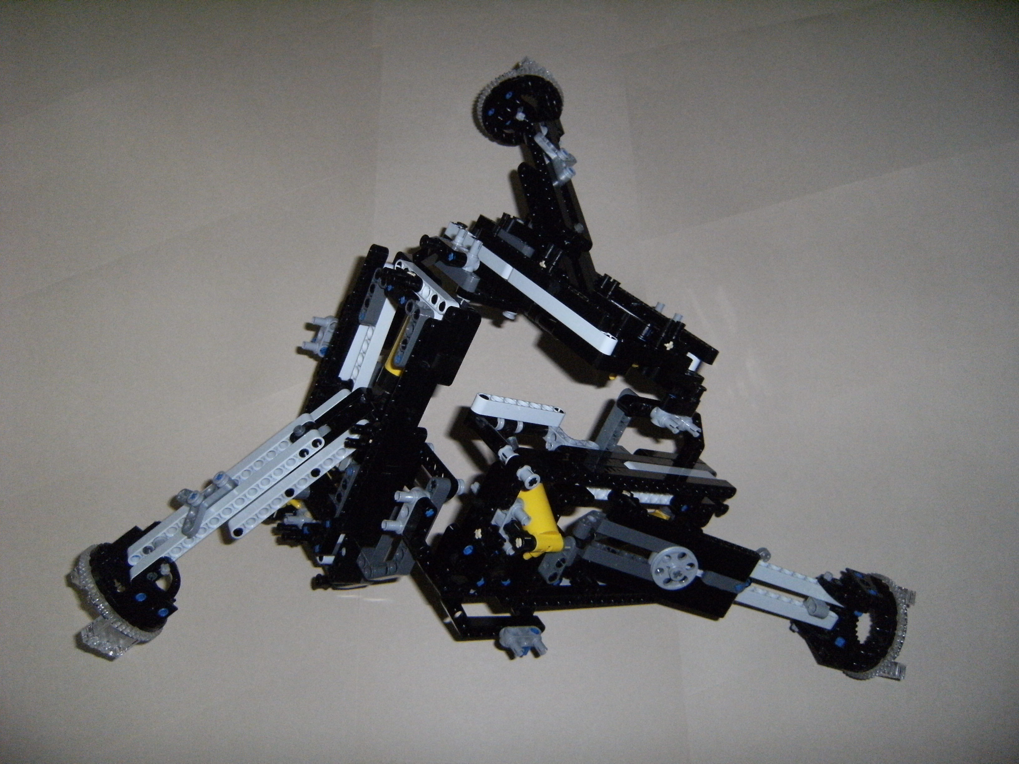
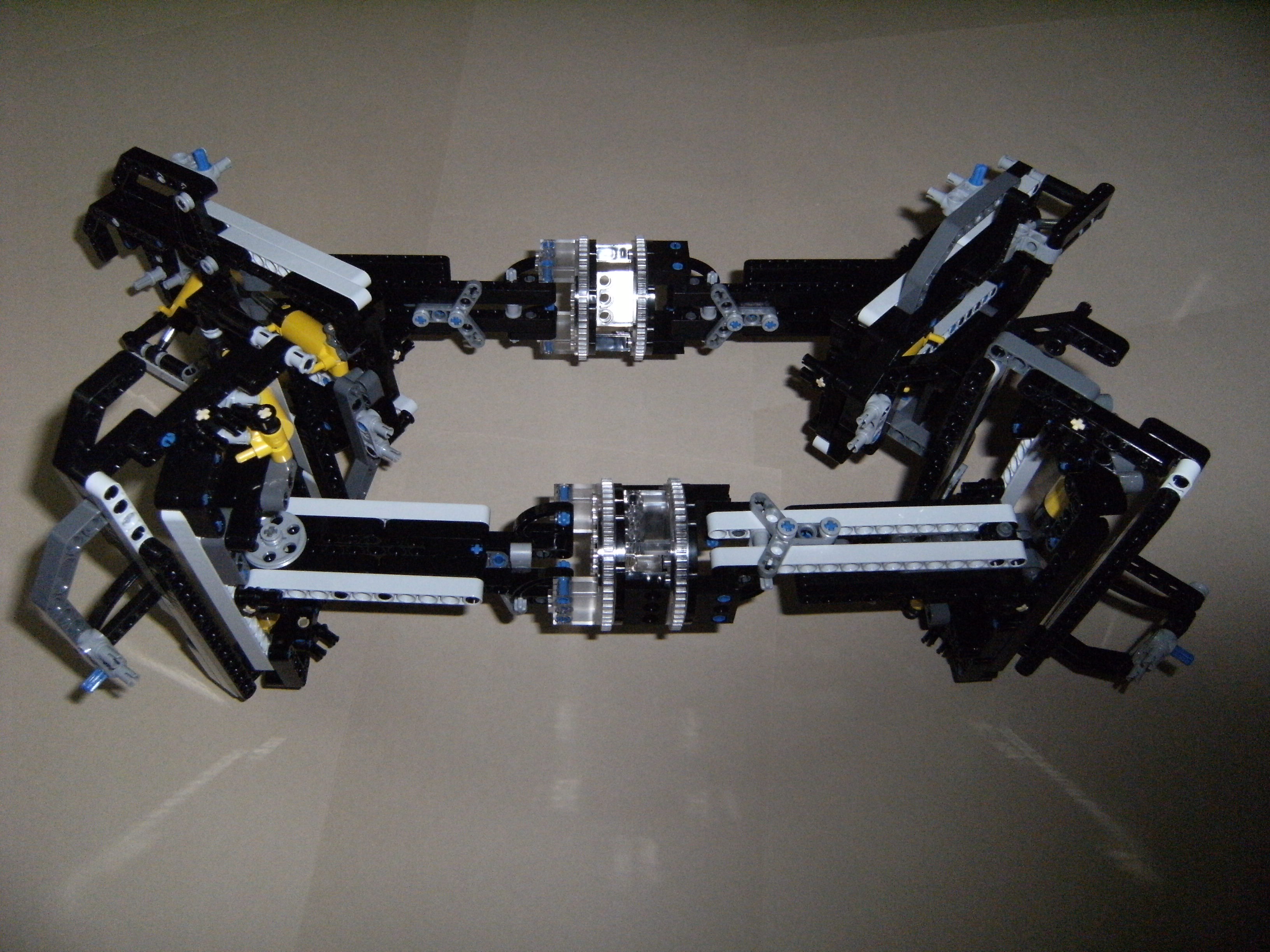
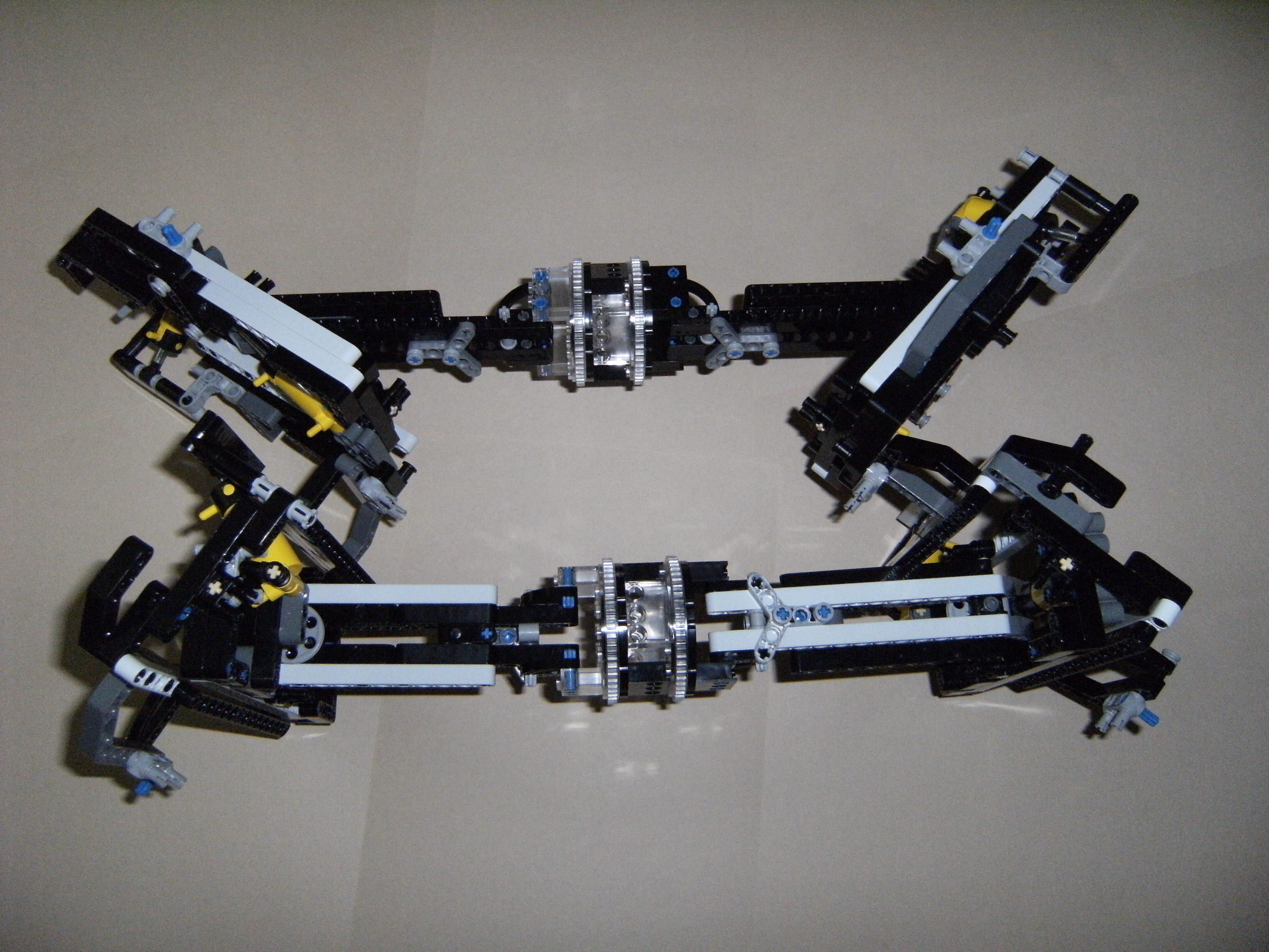
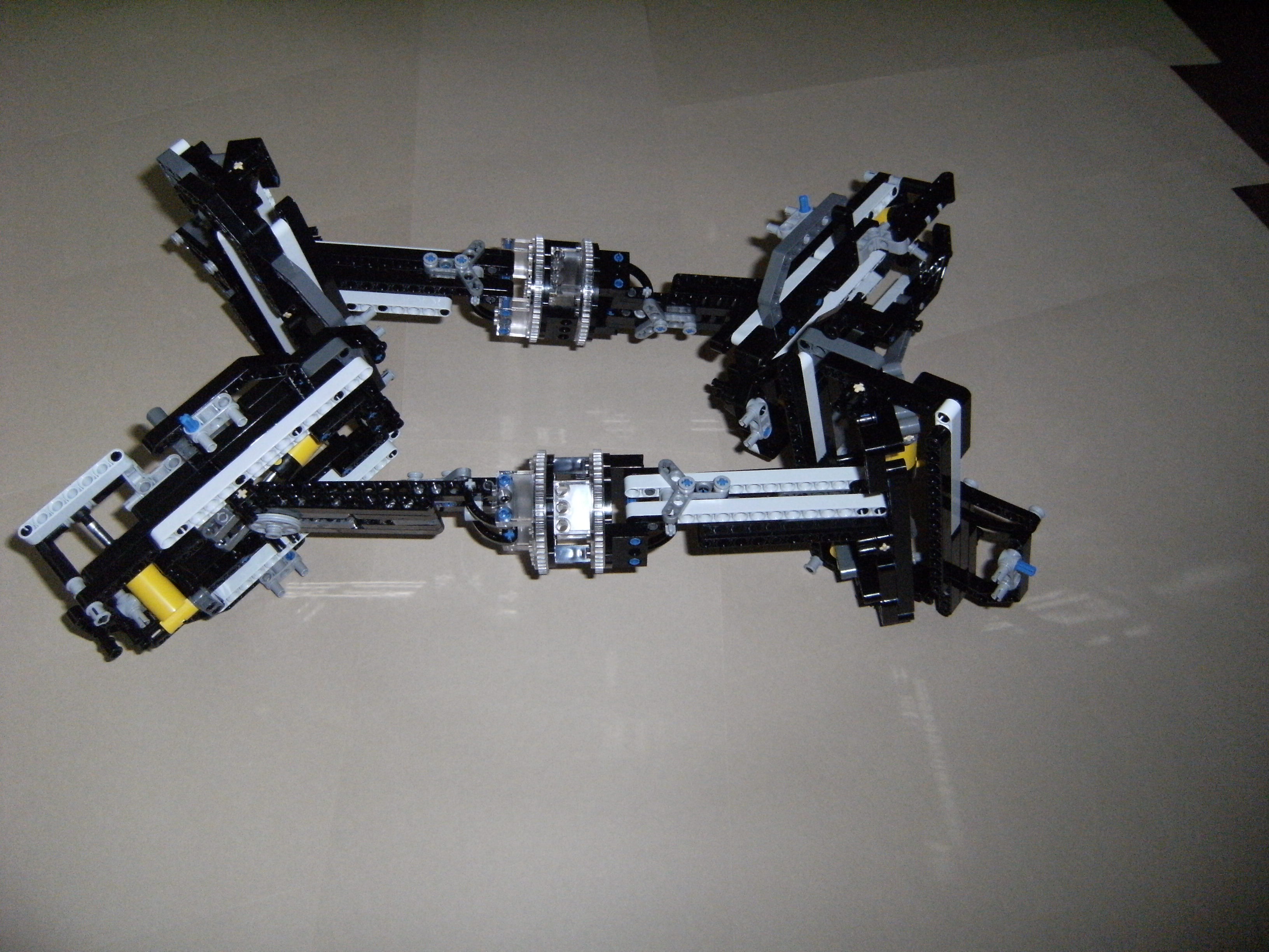
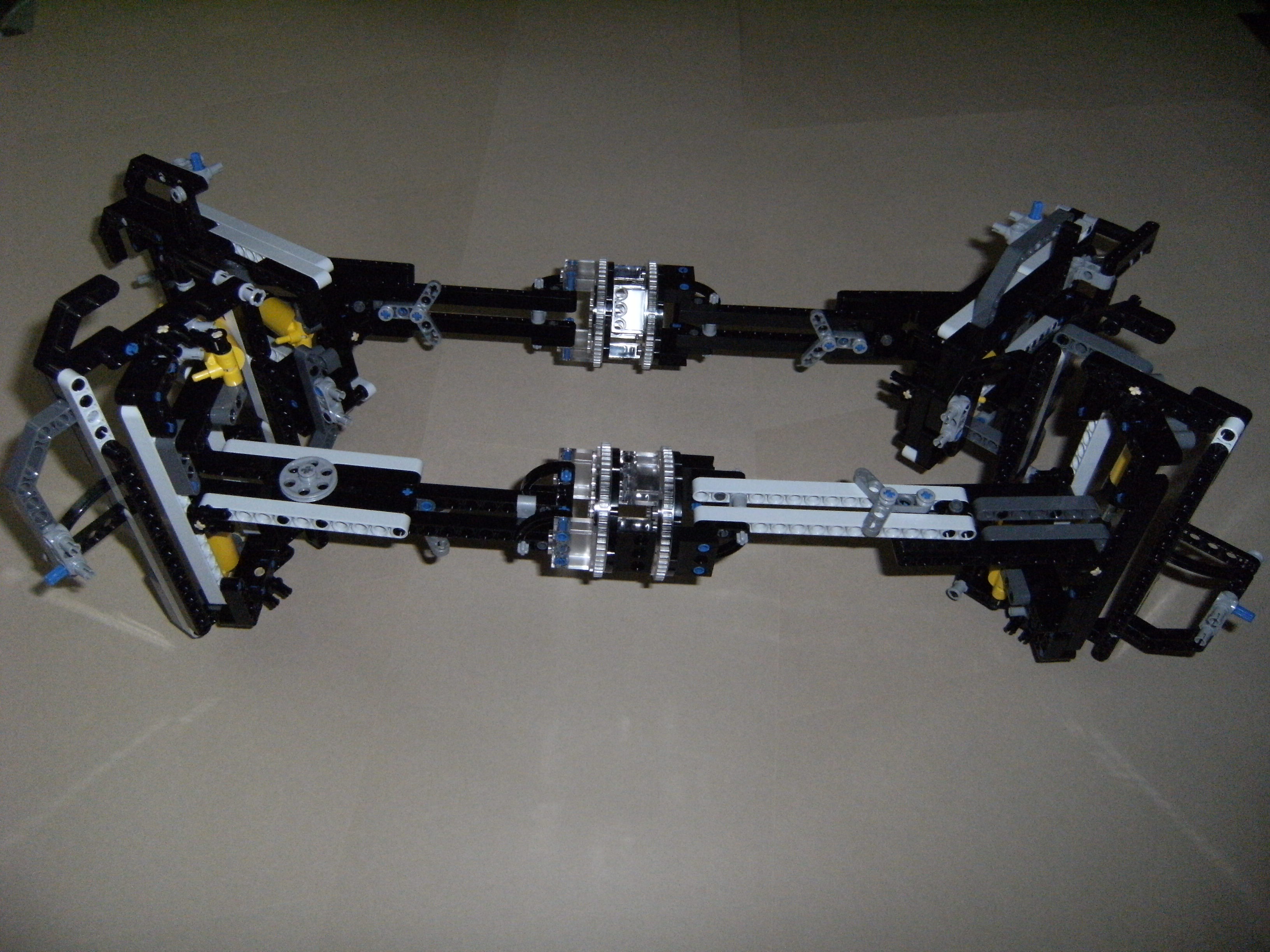
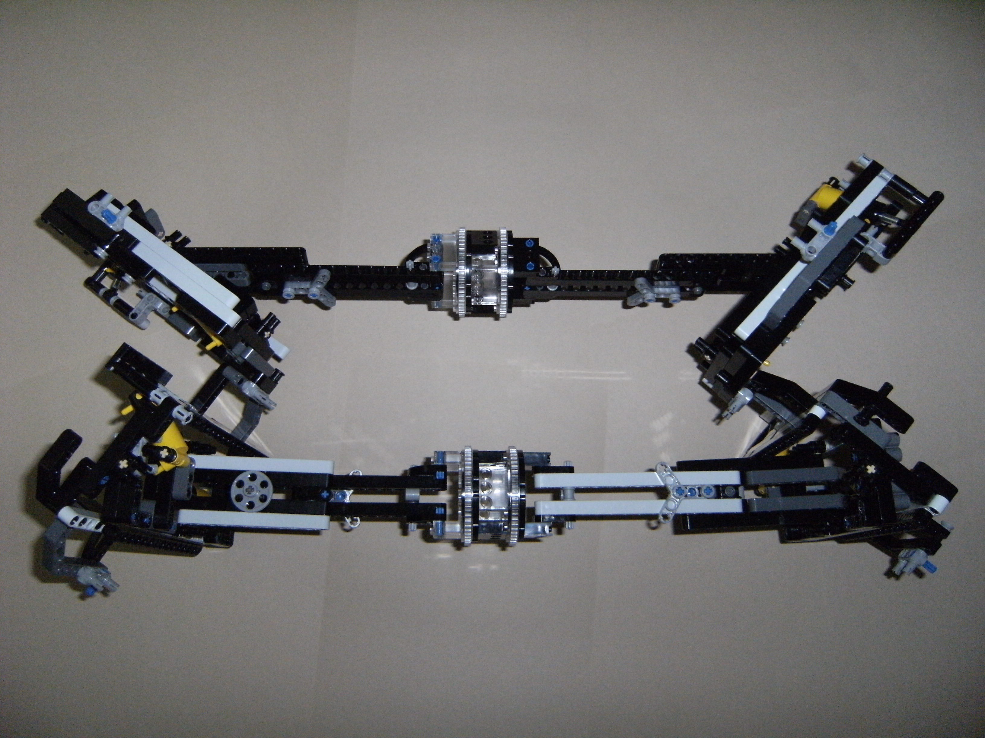
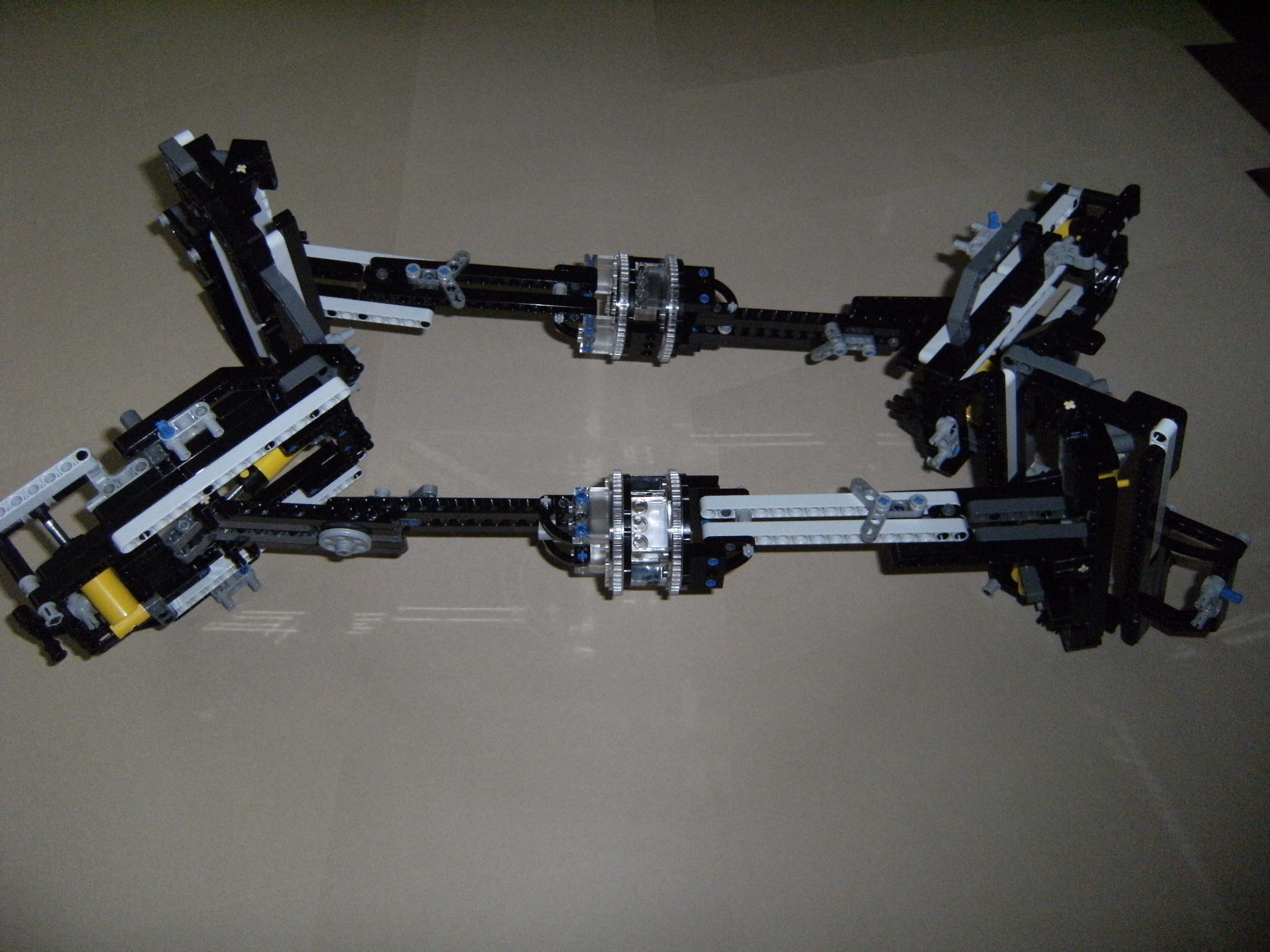
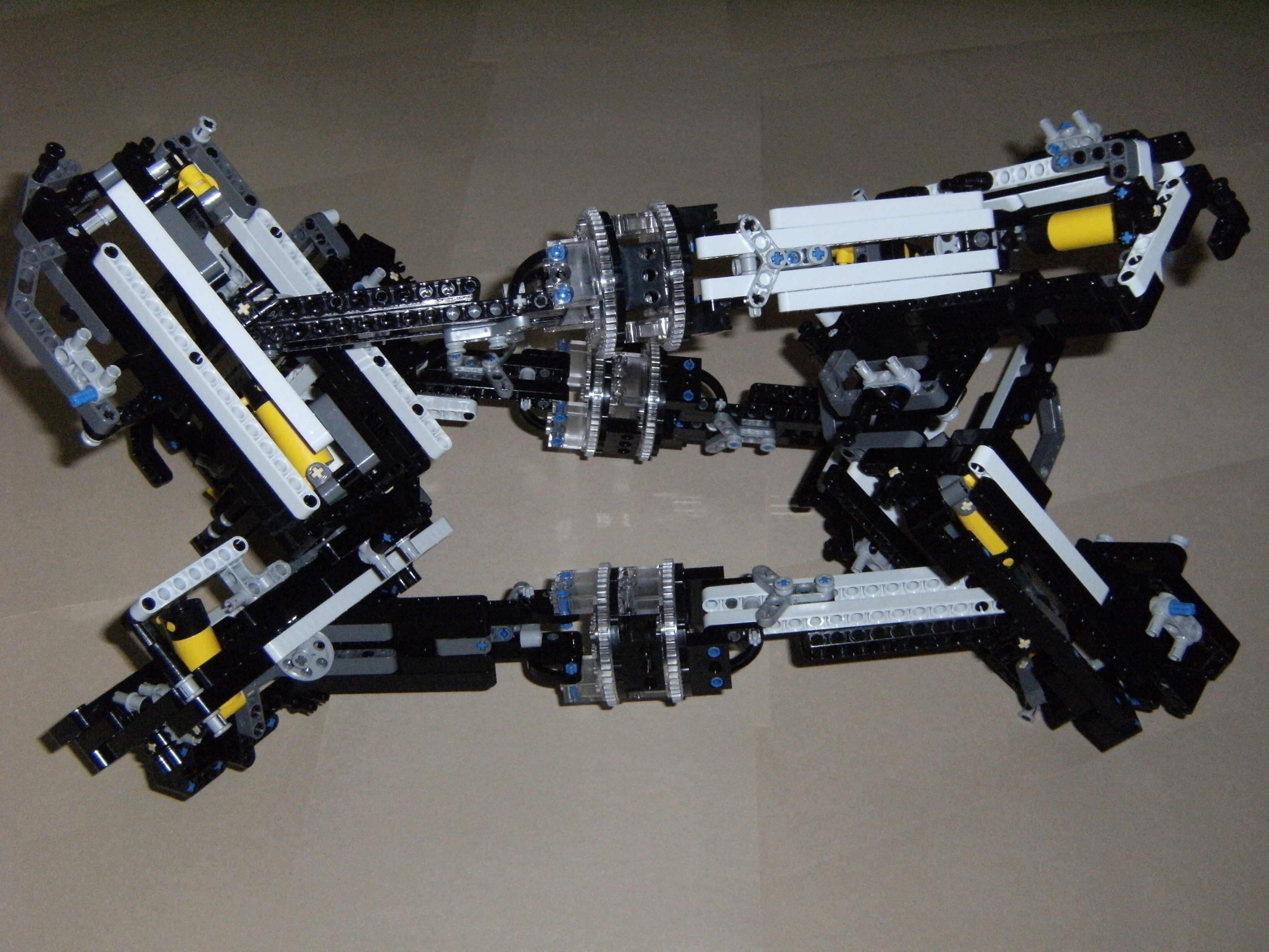
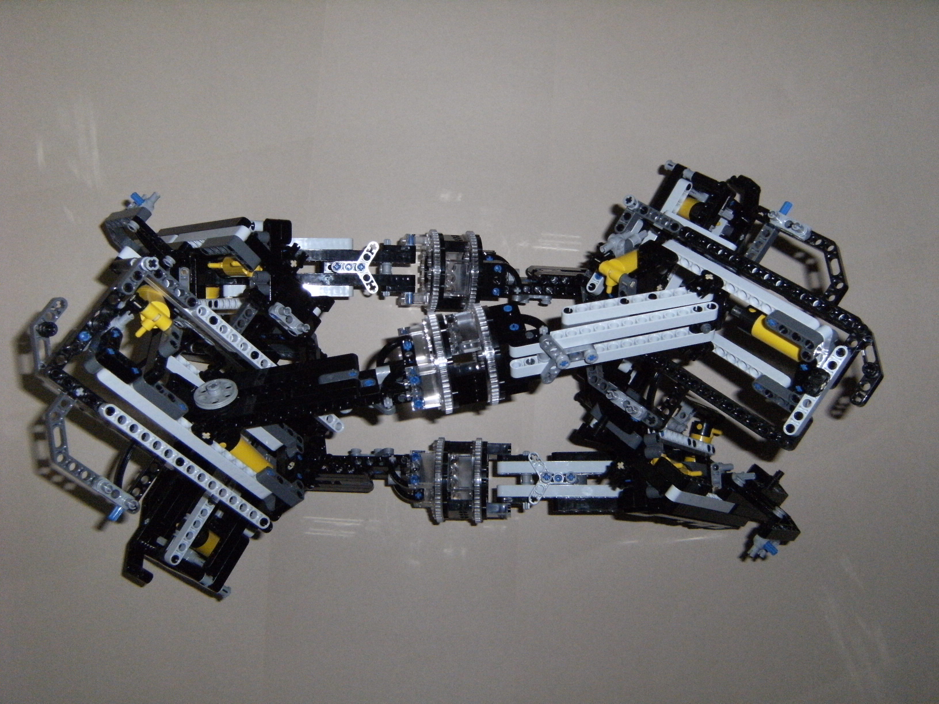
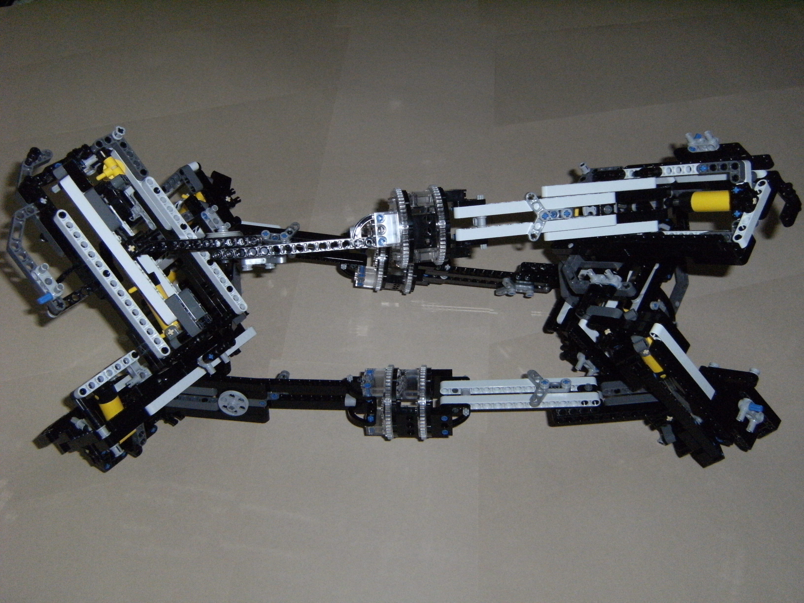
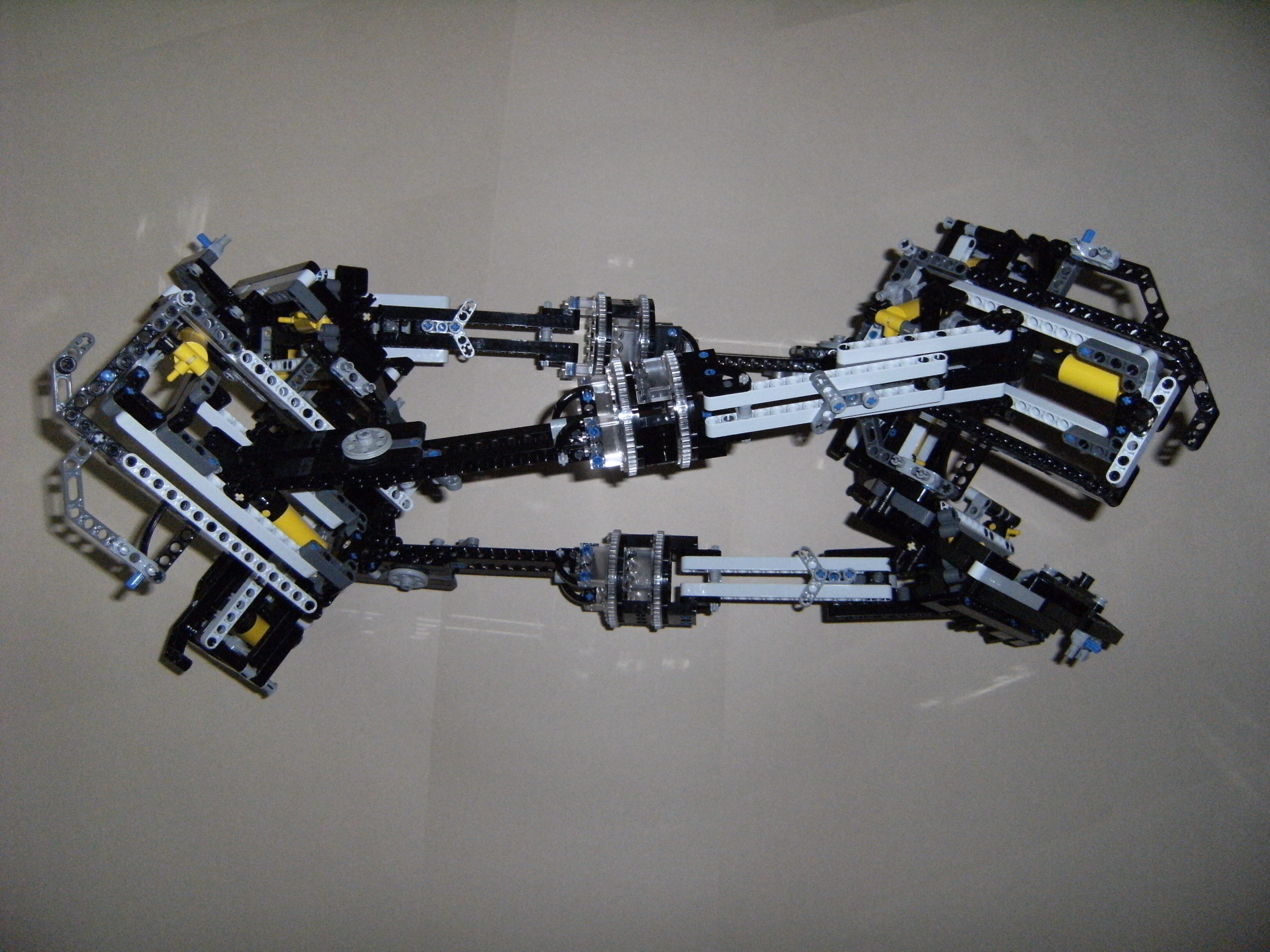
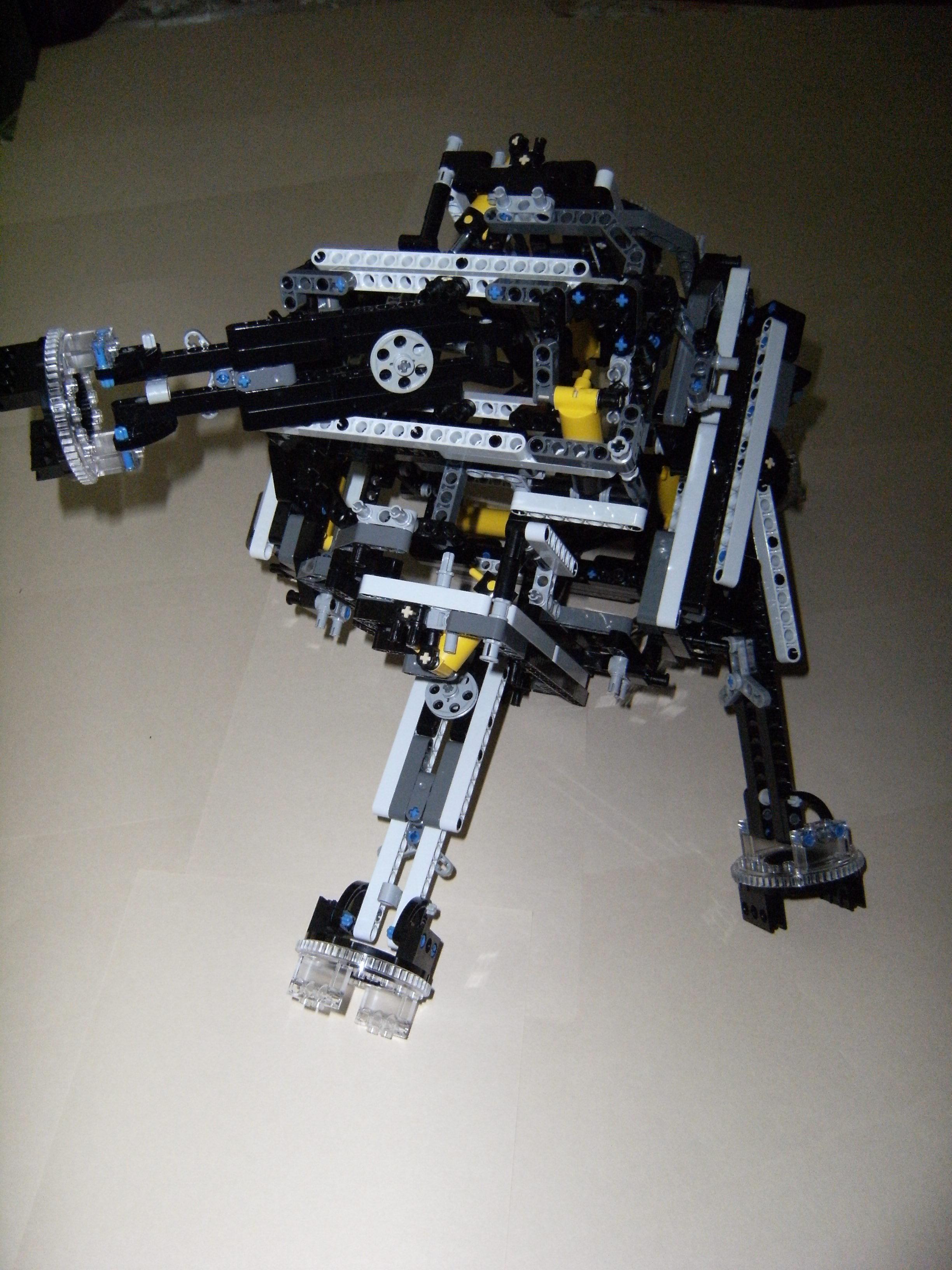
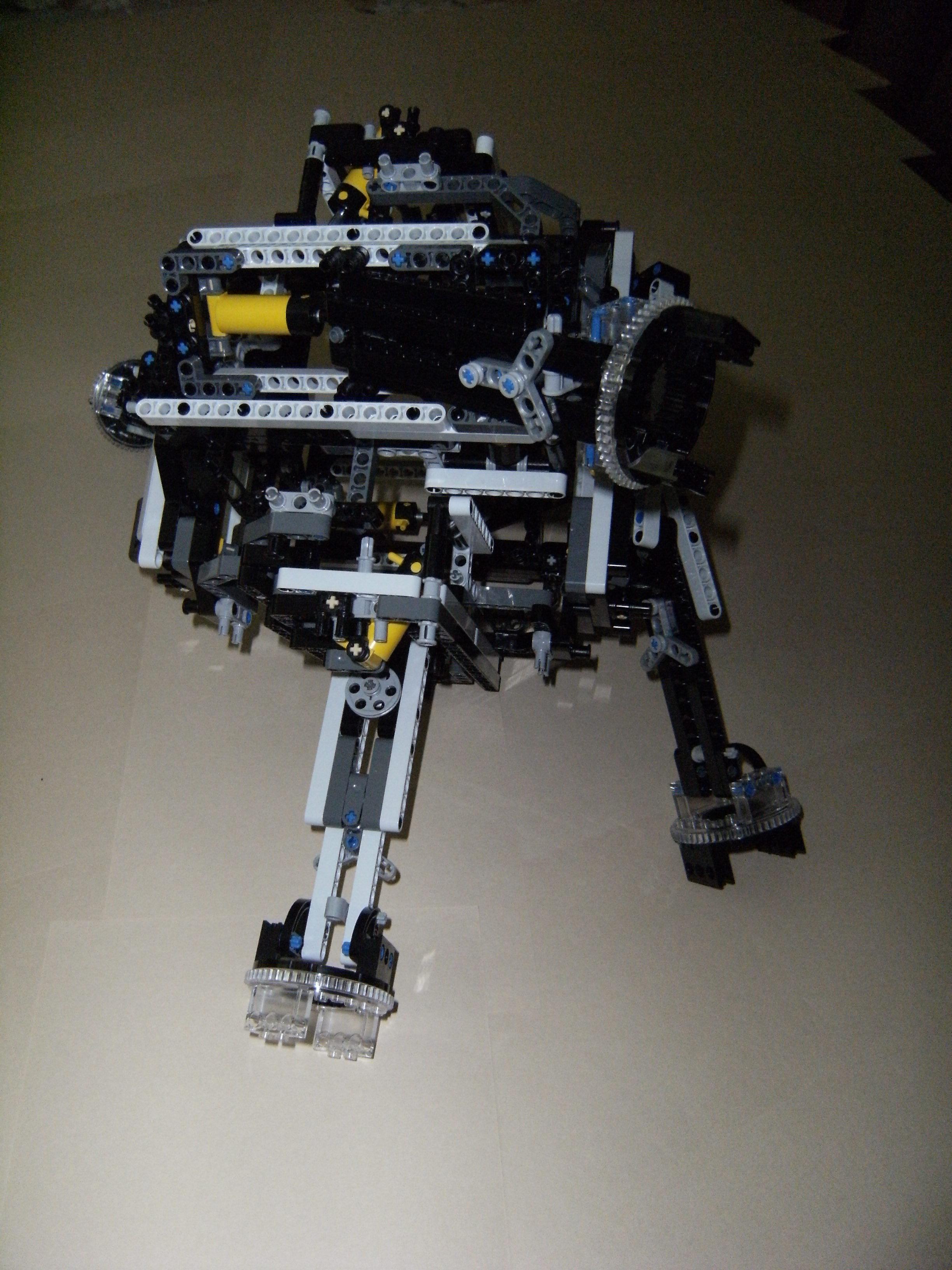
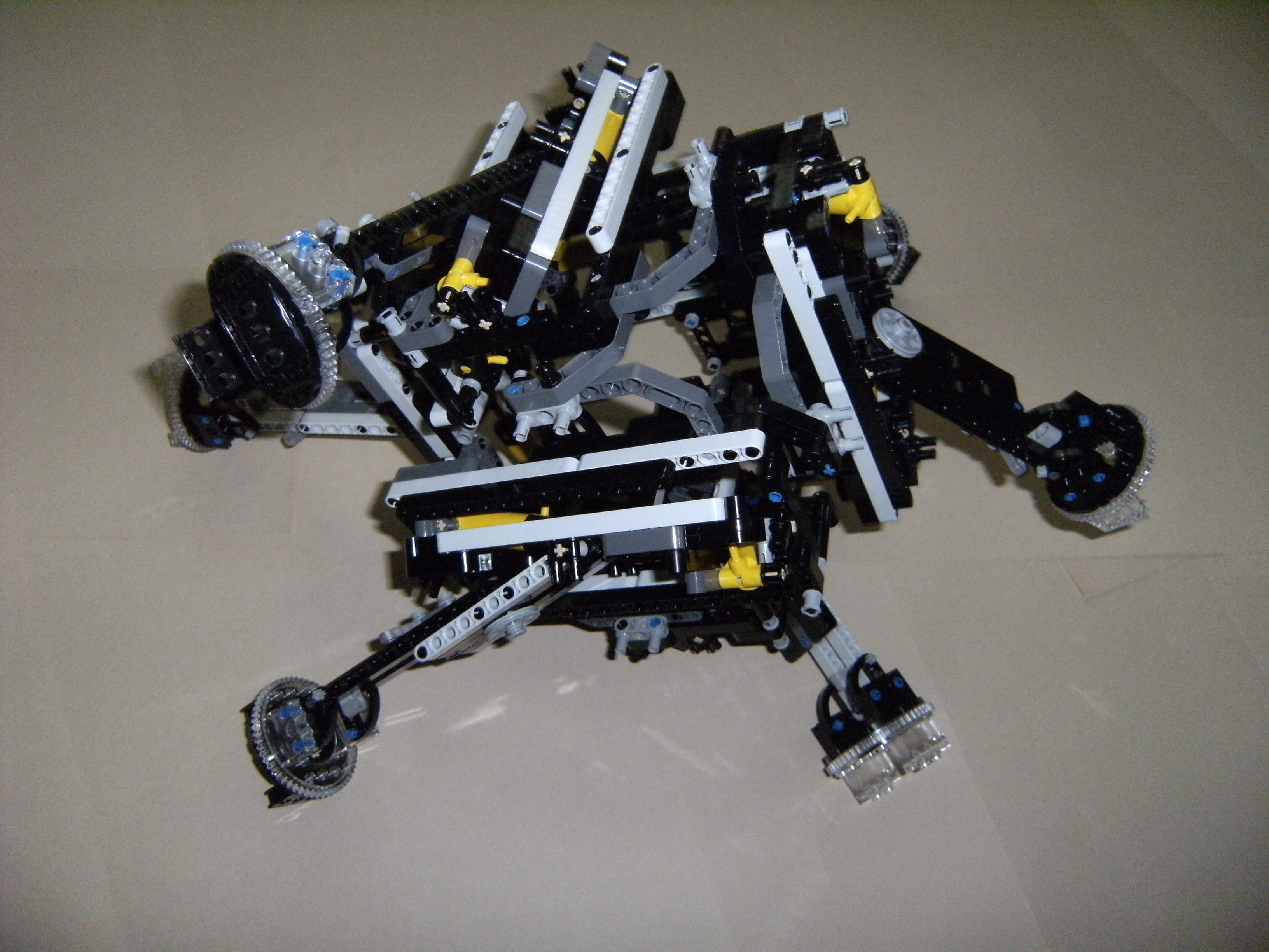
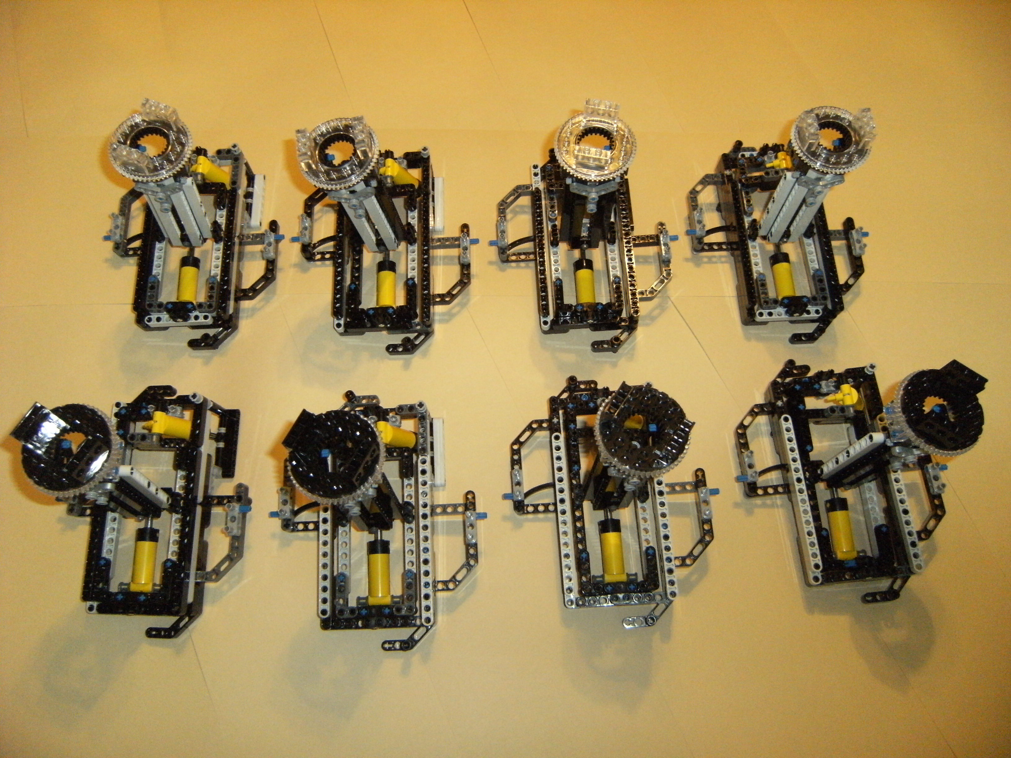
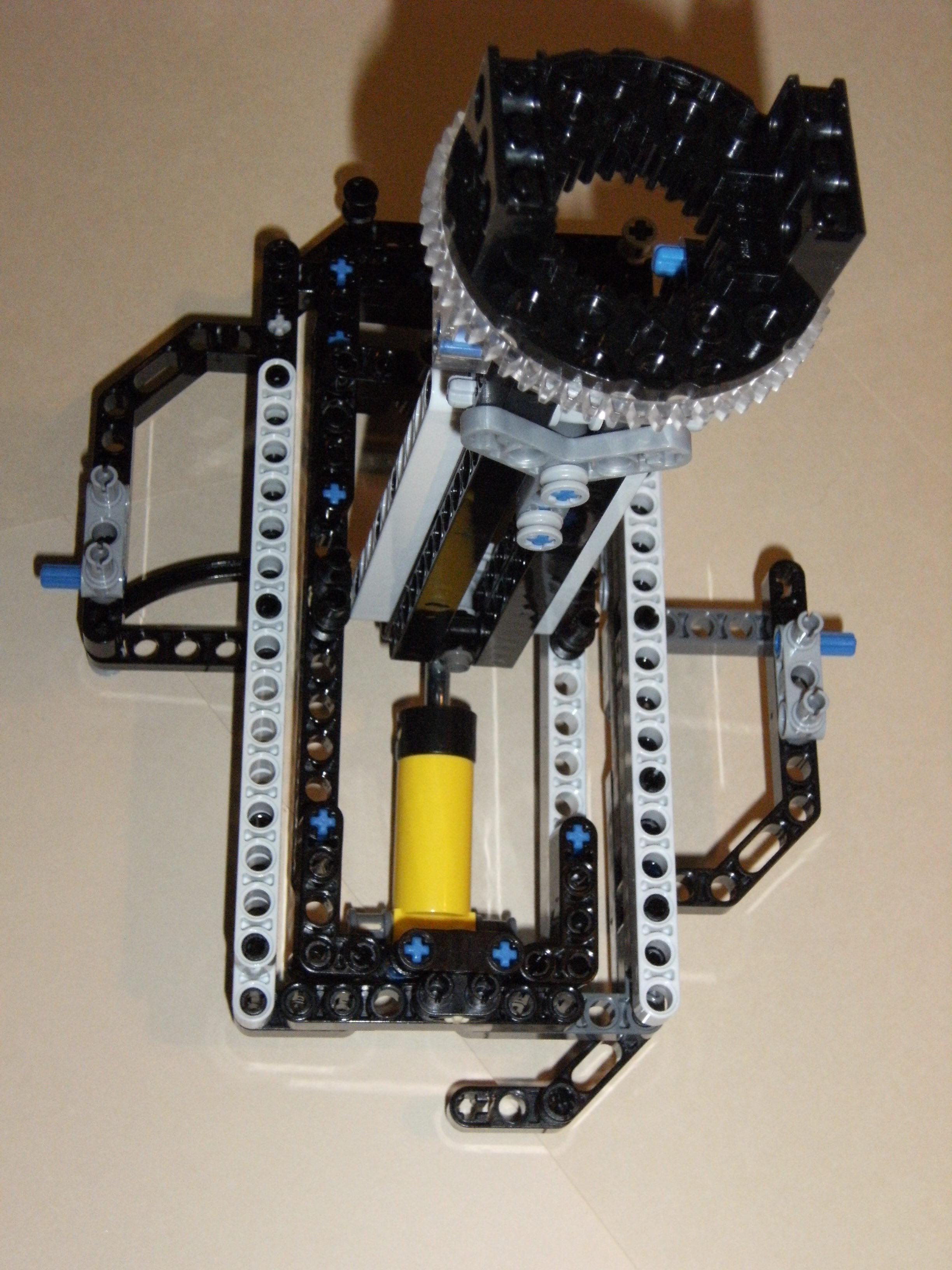
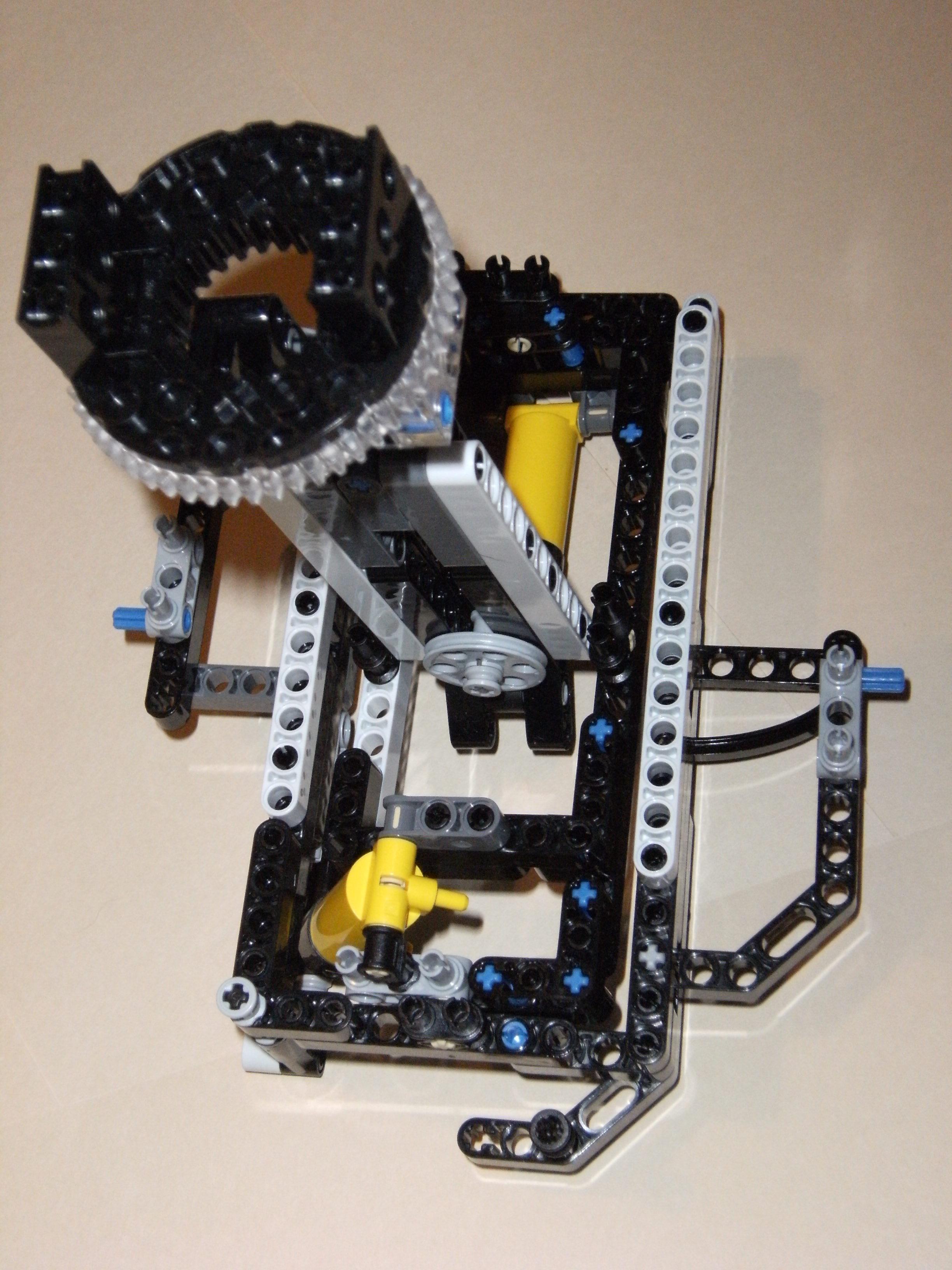
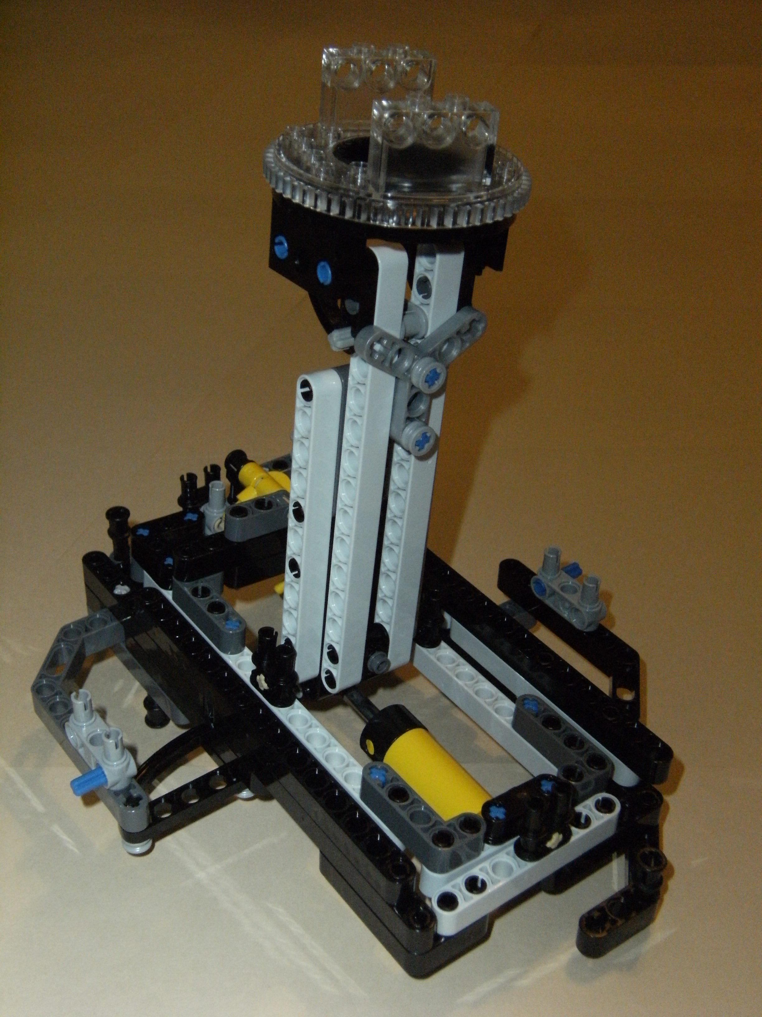
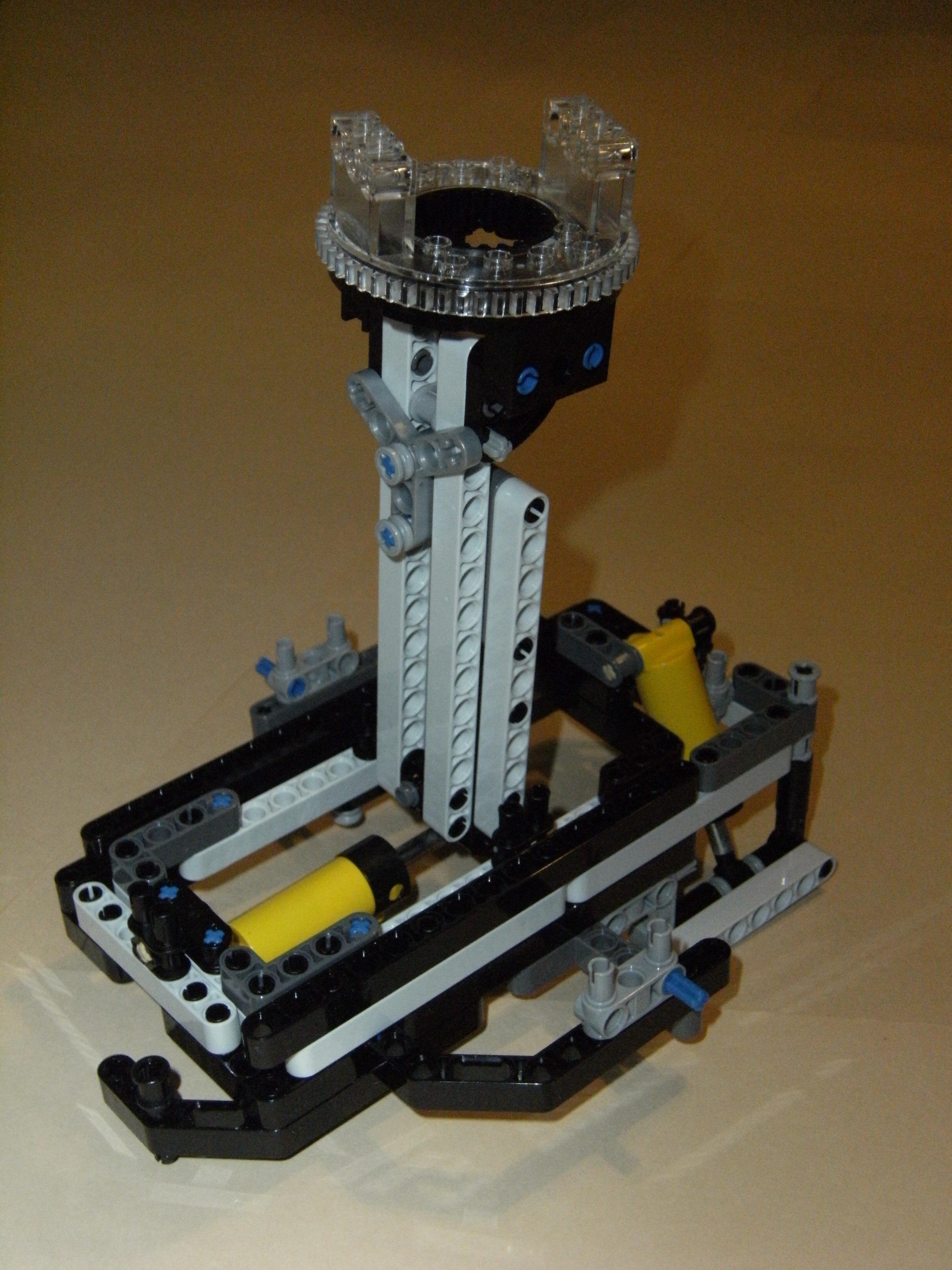
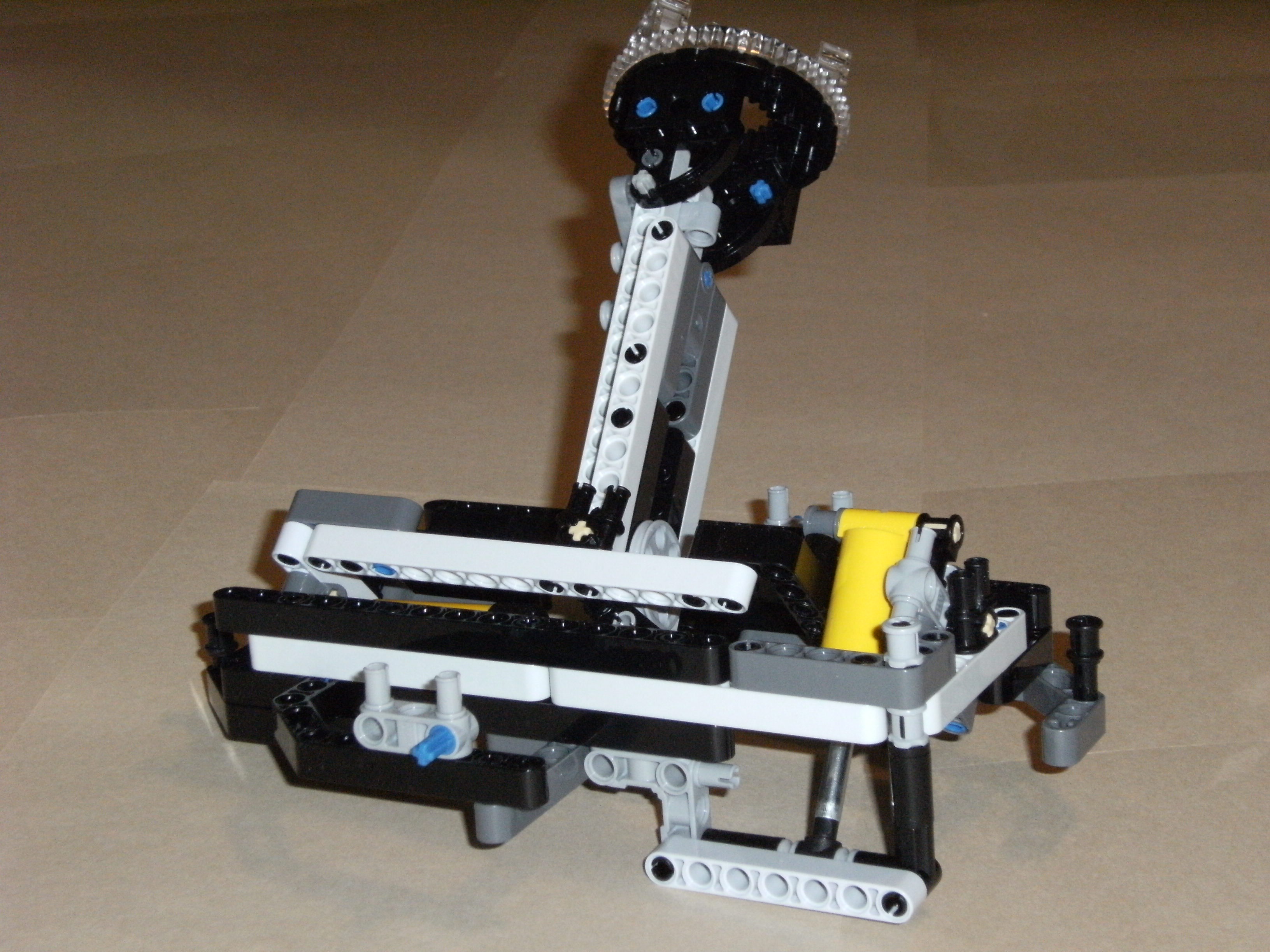
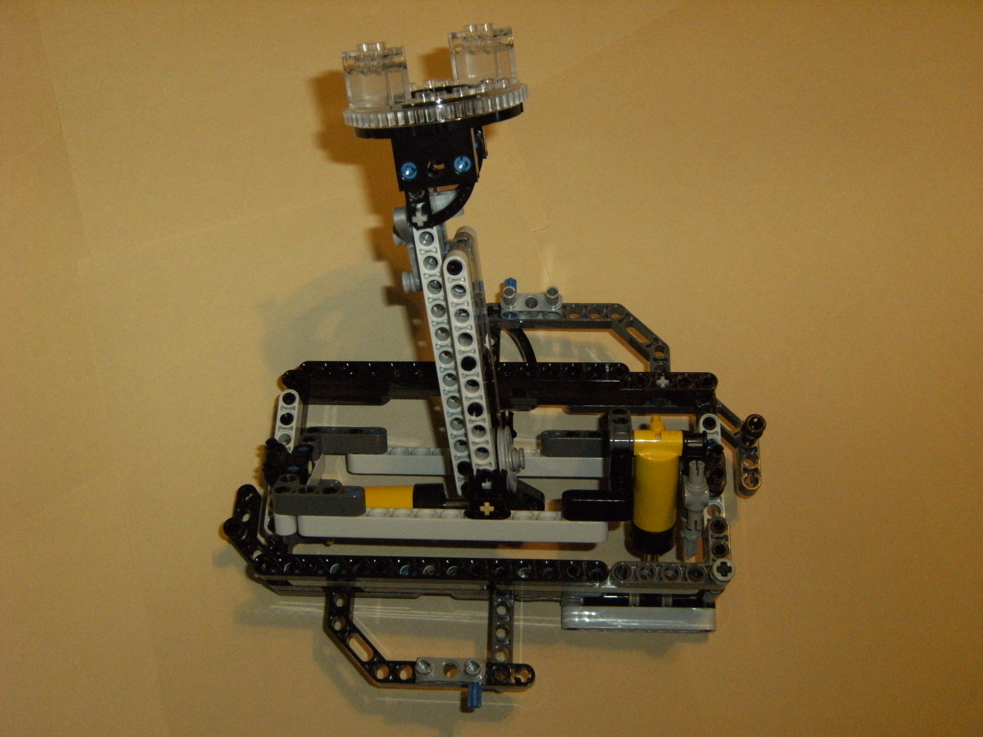
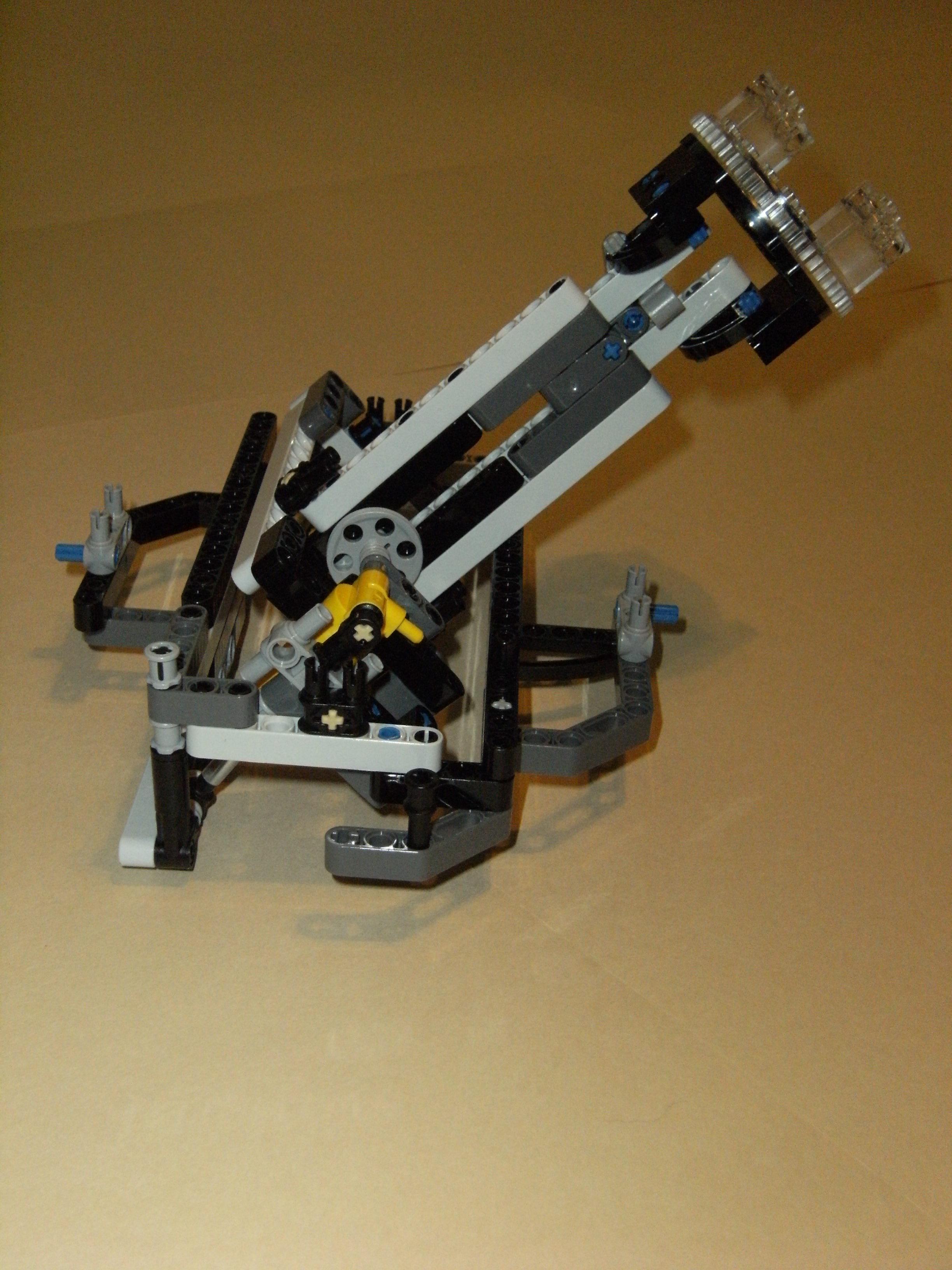
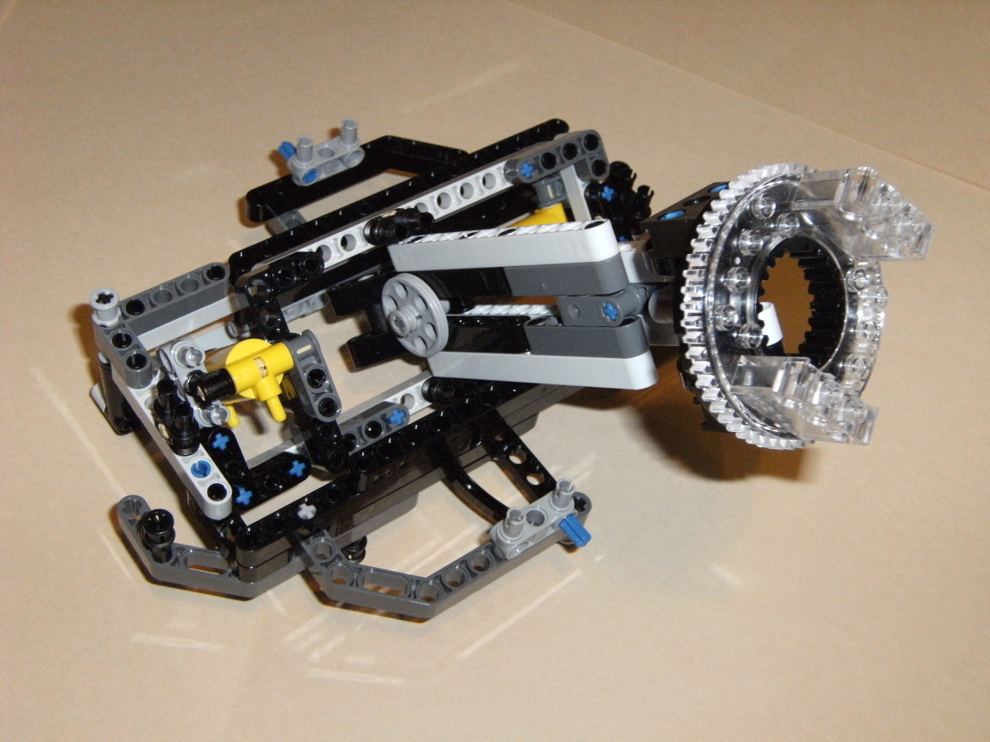
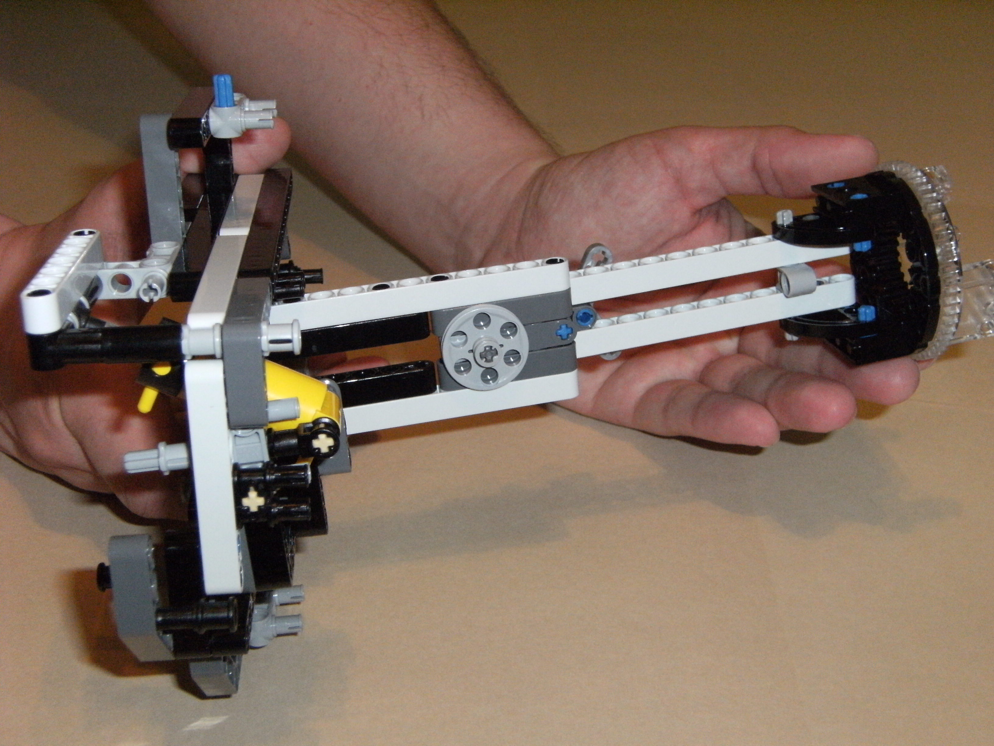
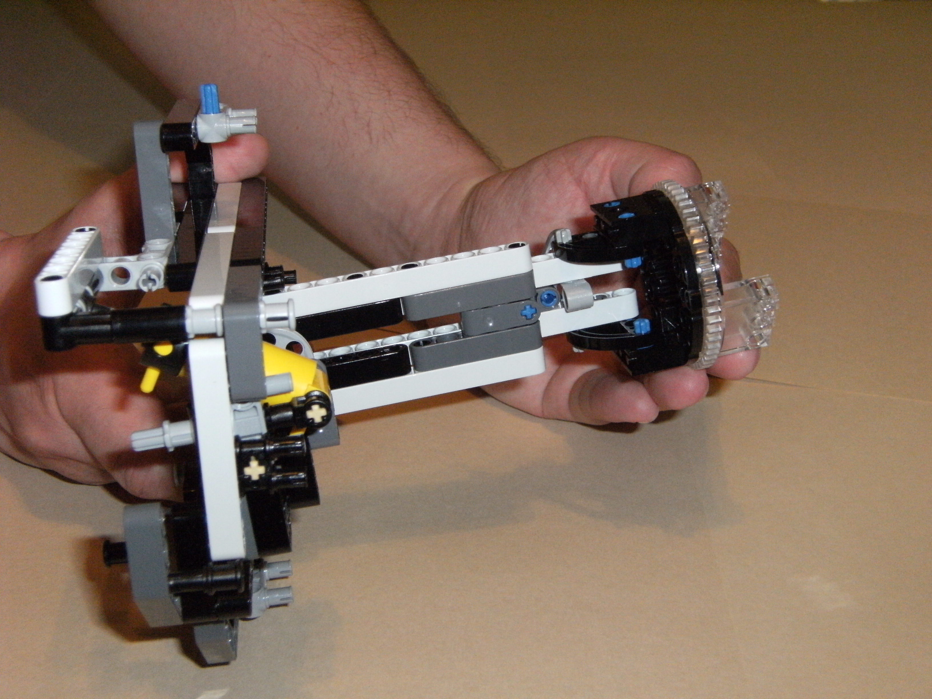
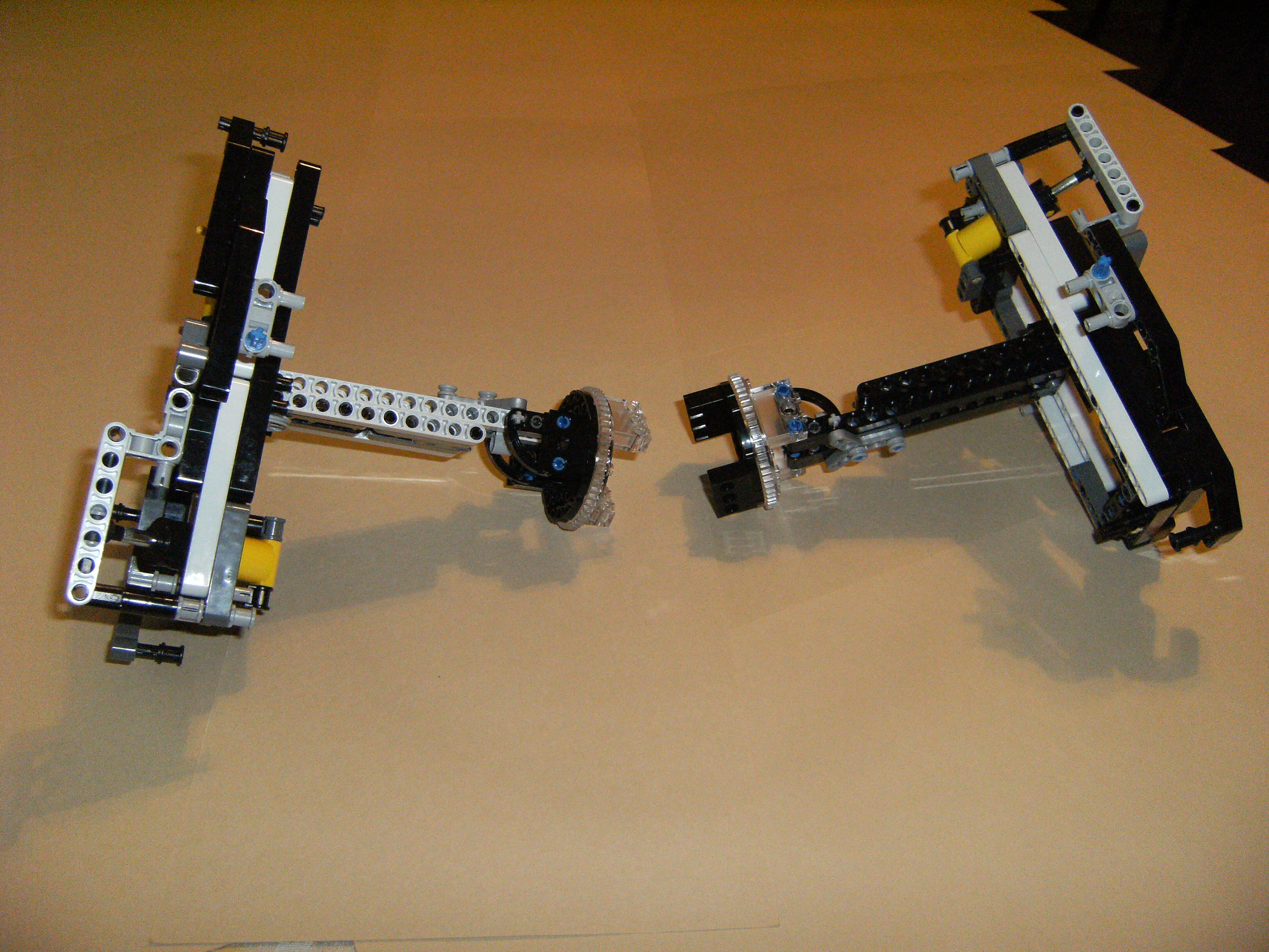
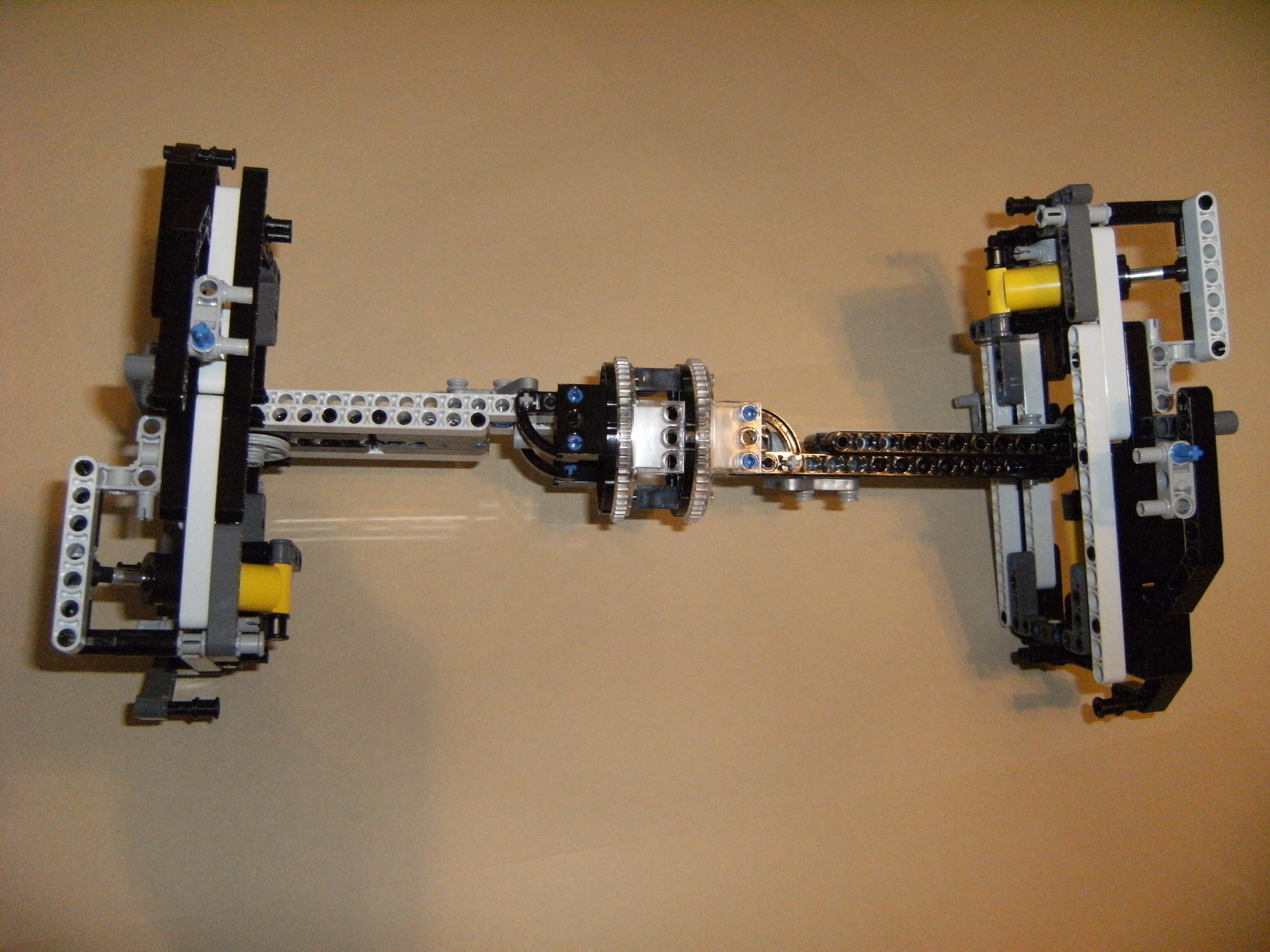
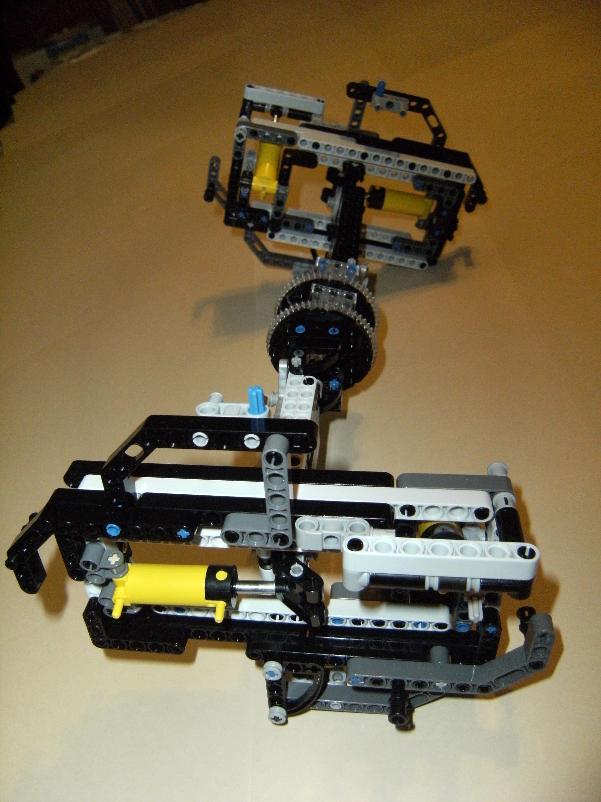
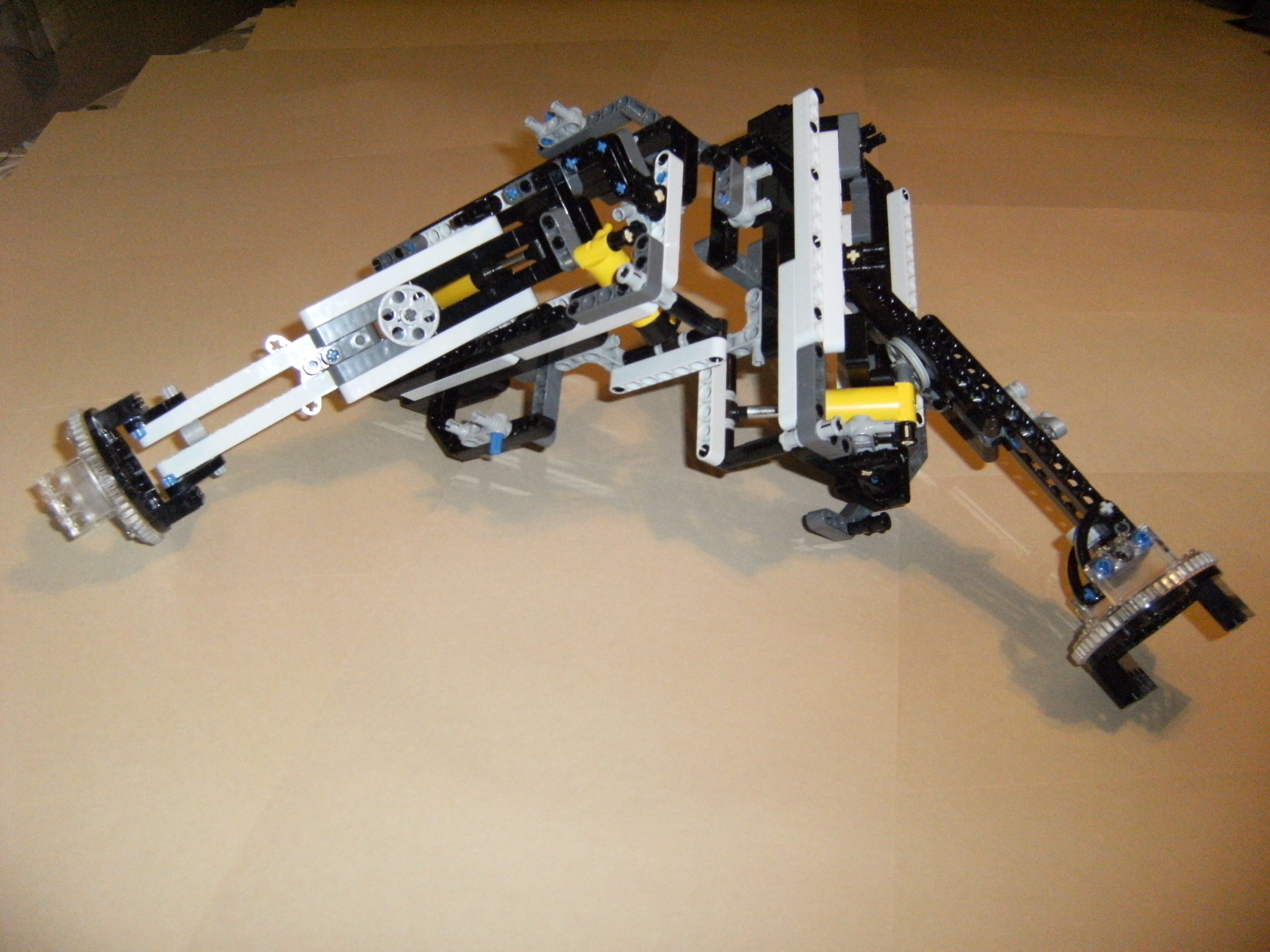
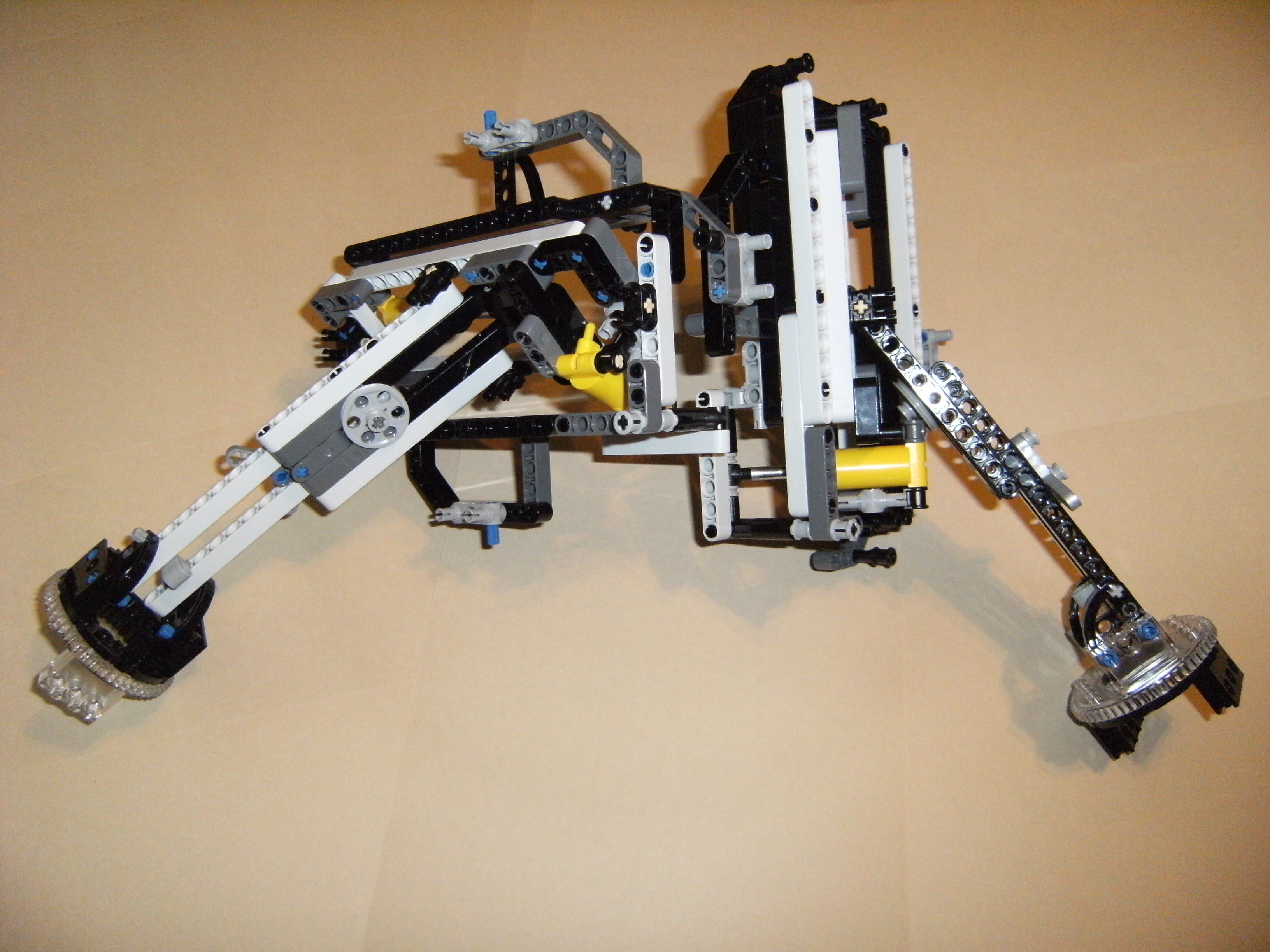
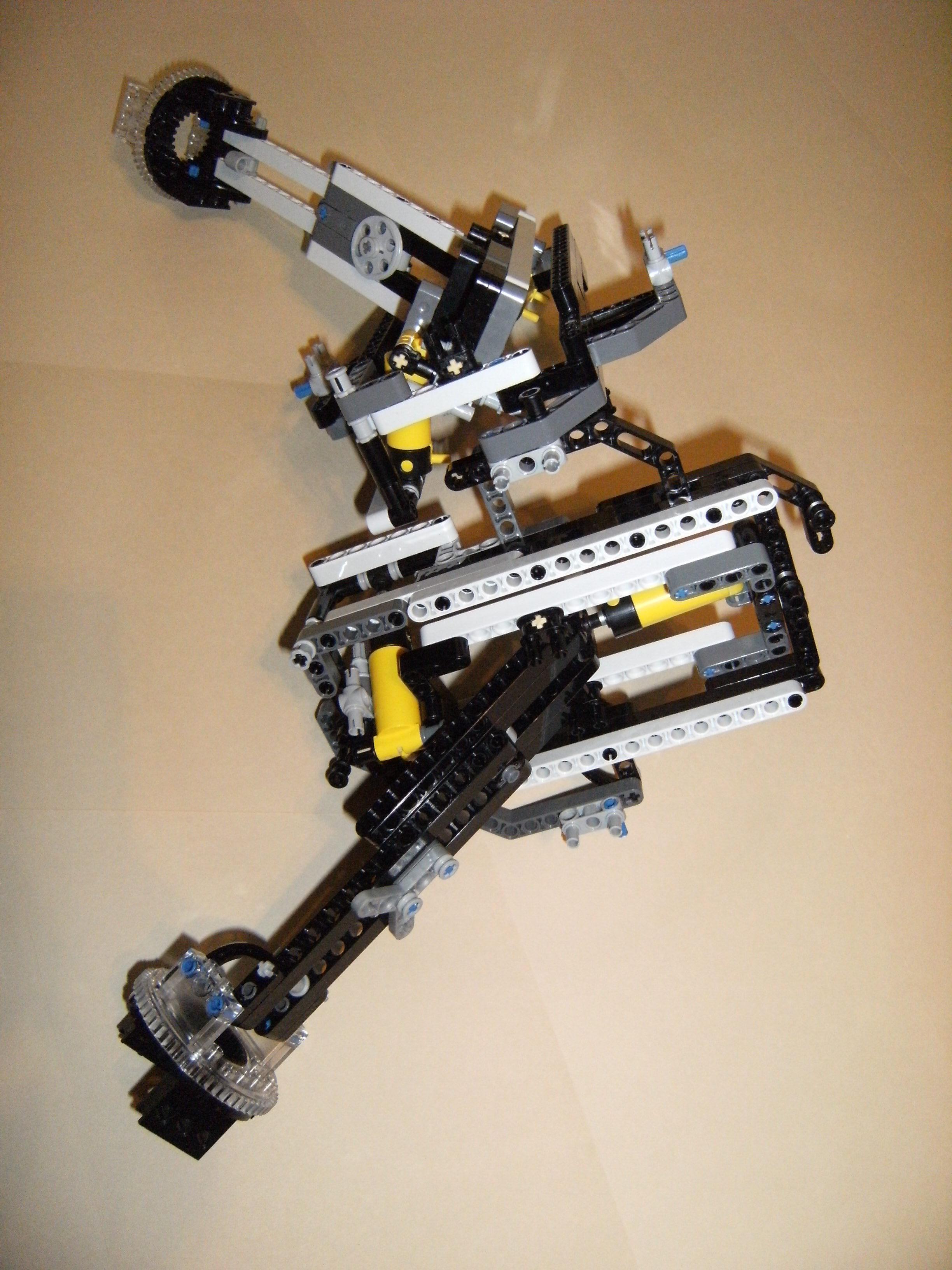
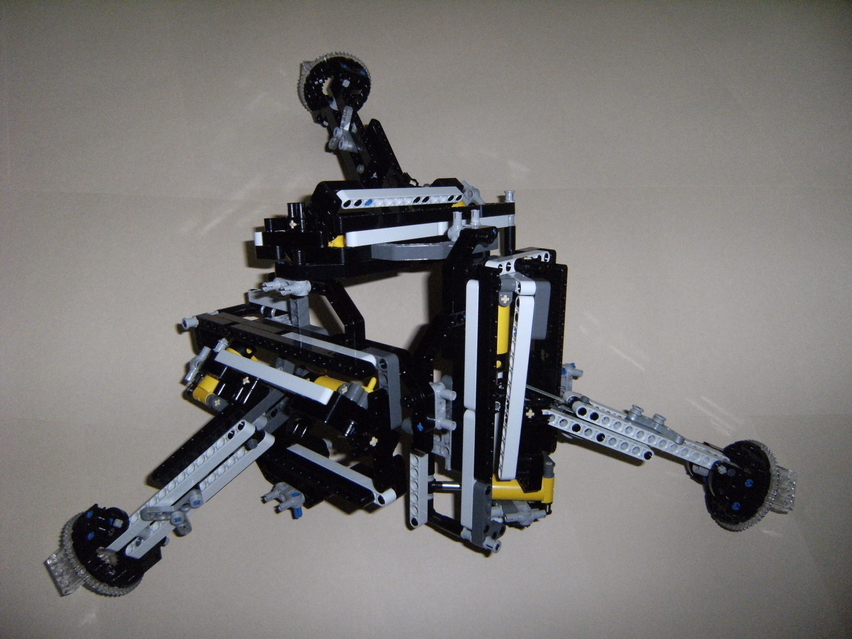
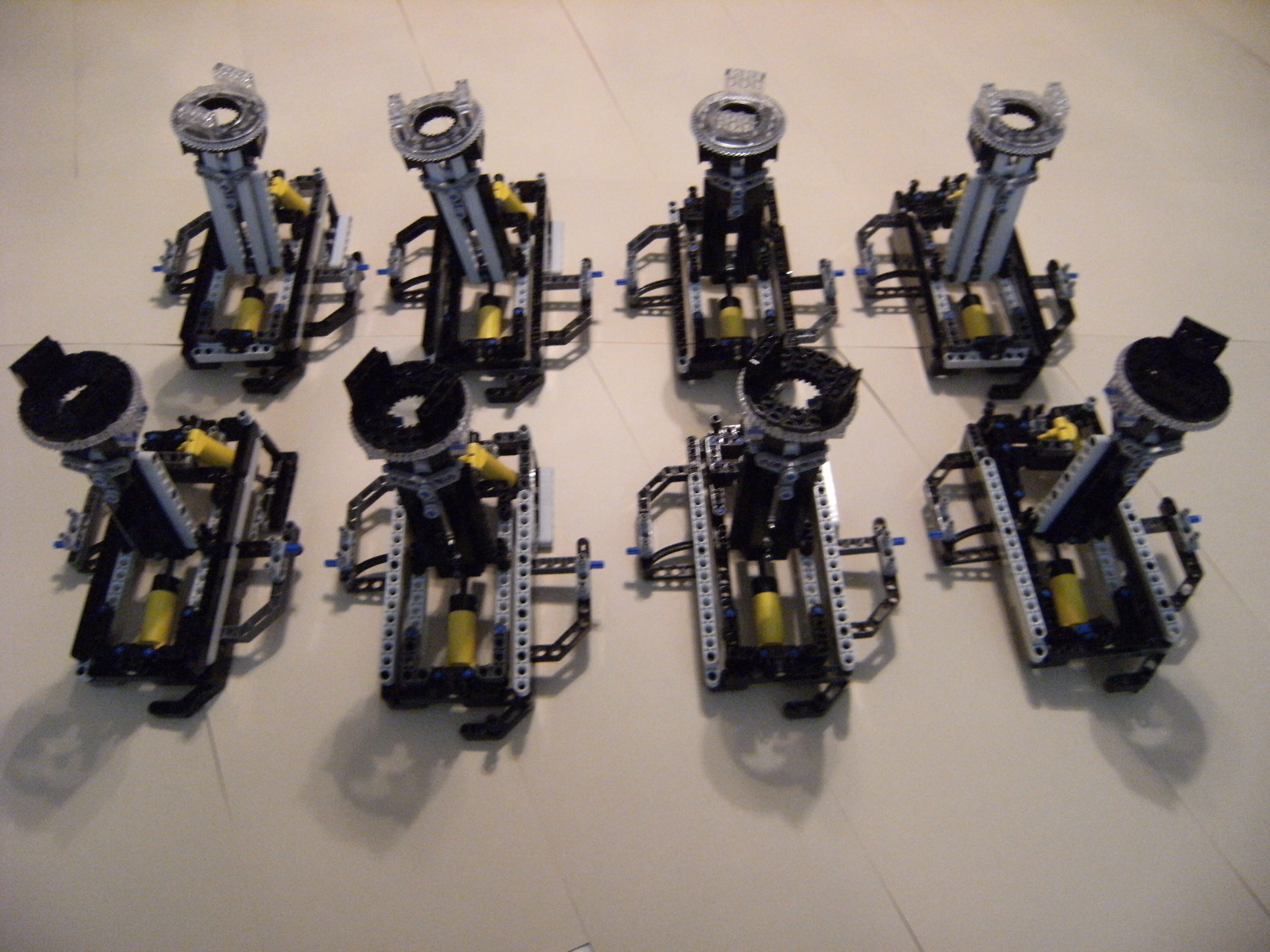
These photos show prototype modules connected in triangular and rectangular loop patterns.
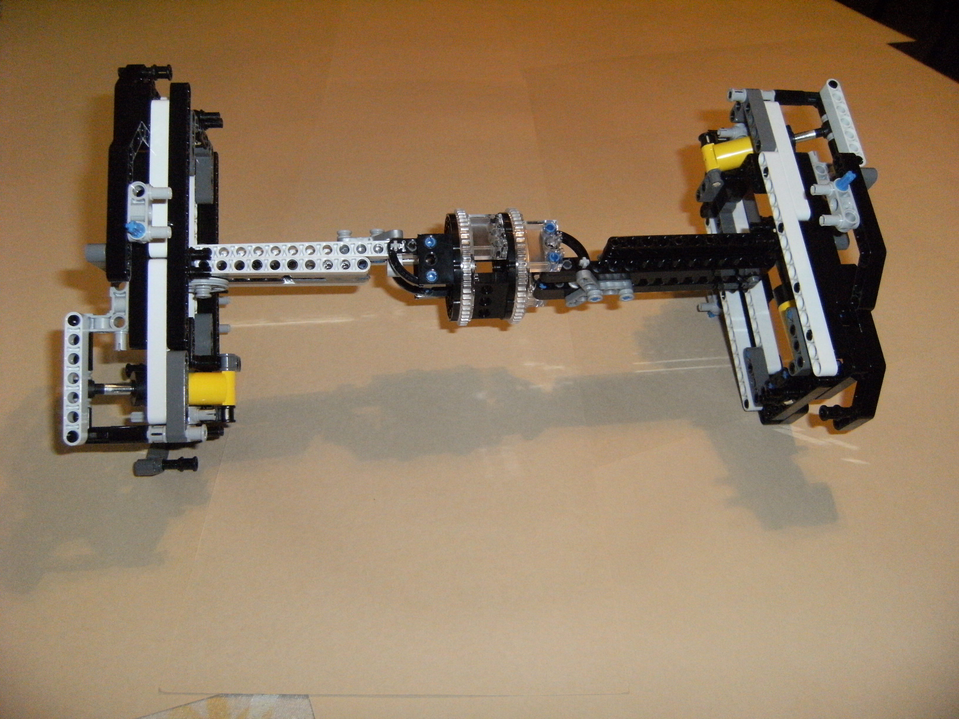
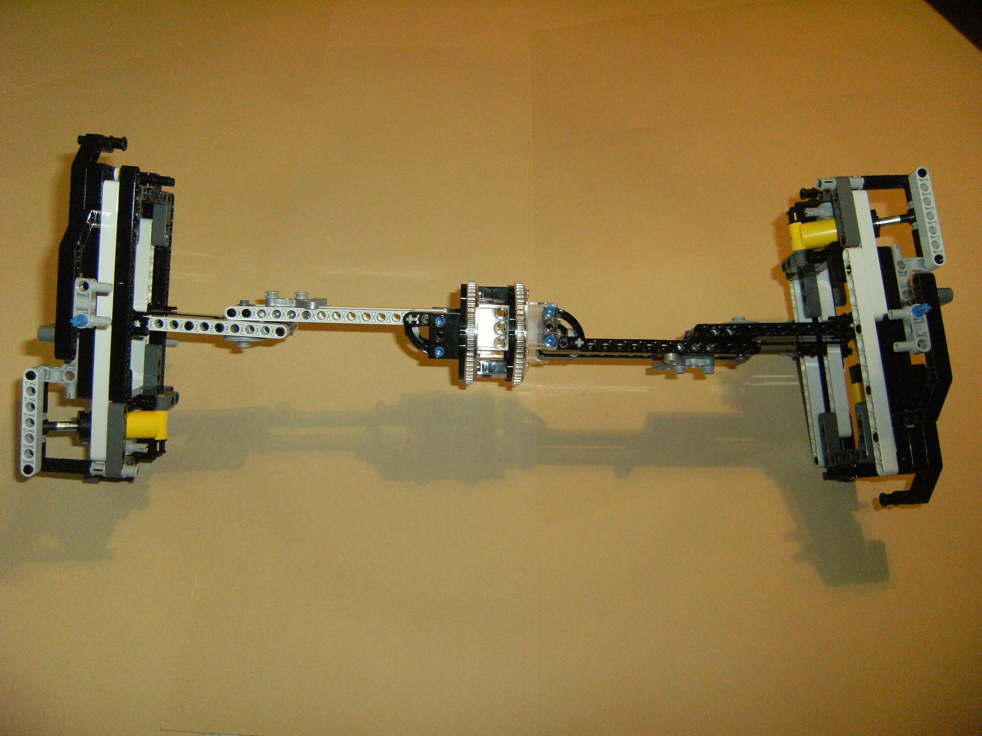
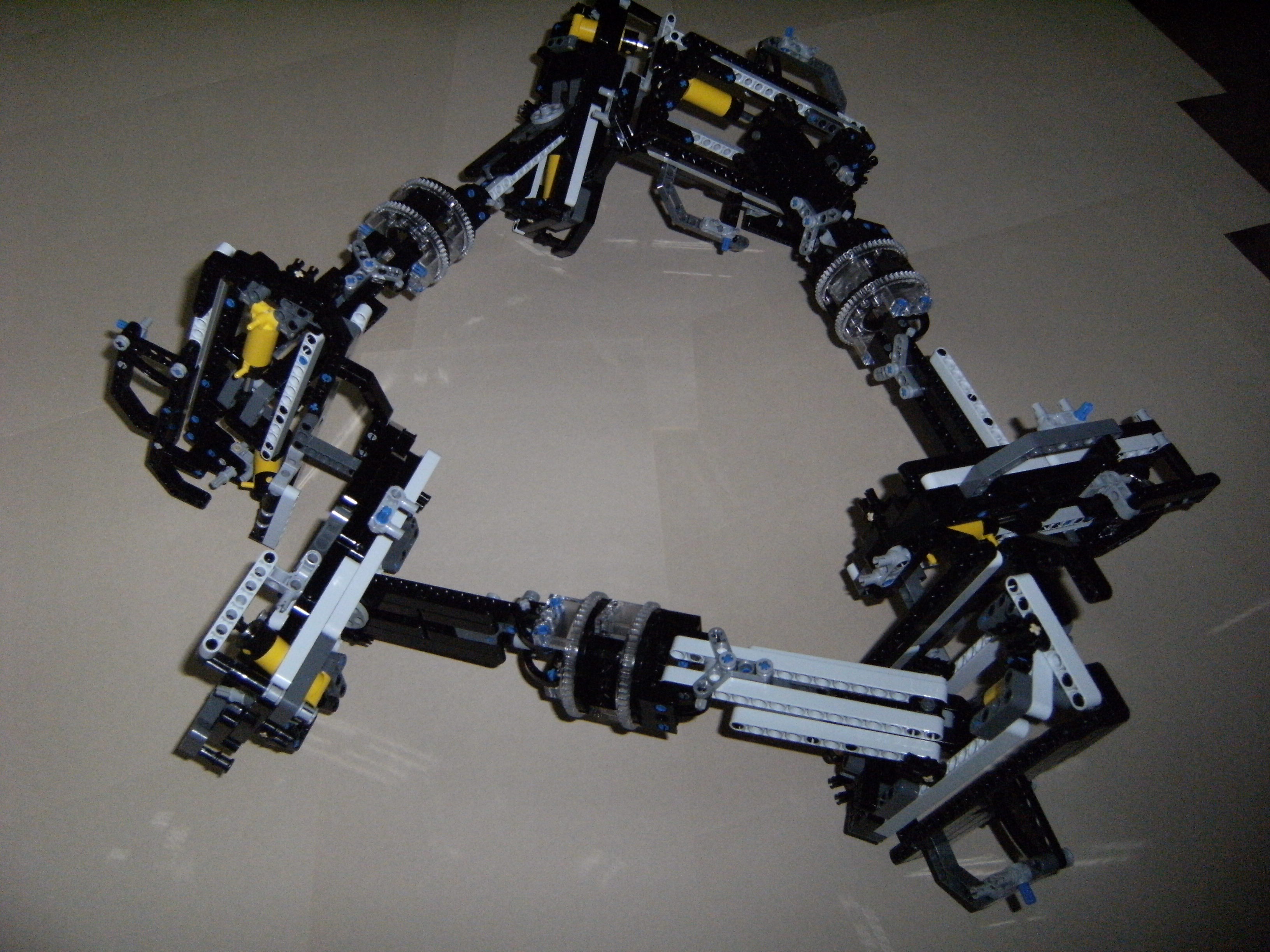 Set of six modules connected in a triangular loop pattern, with all legs fully retracted.
Figure 50. View 1
These photos show prototype modules connected in triangular and rectangular loop patterns.
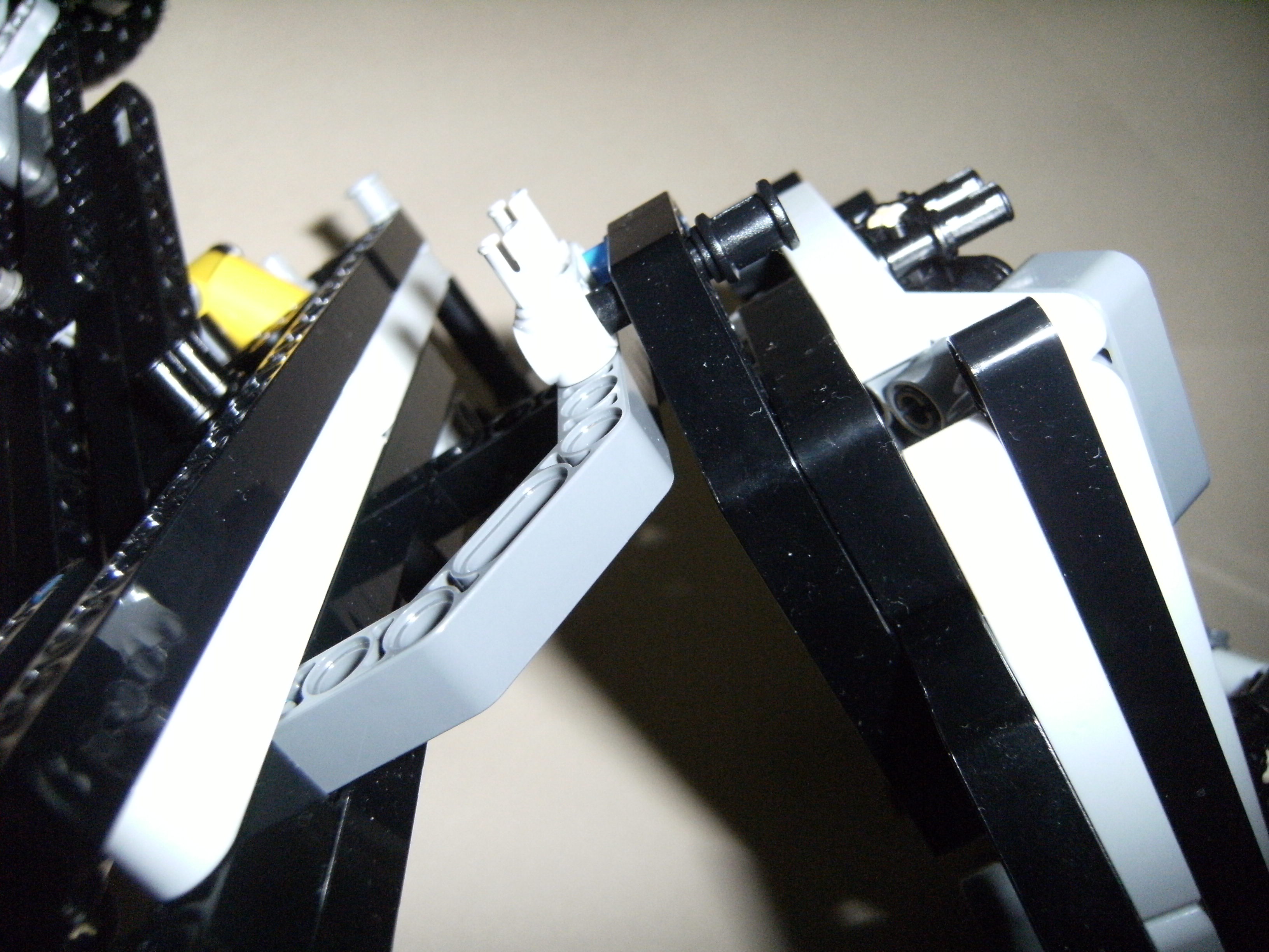
These photos show prototype modules connected to form partial or complete cells, and cell interconnections.
| [EMBED VIDEO HERE]
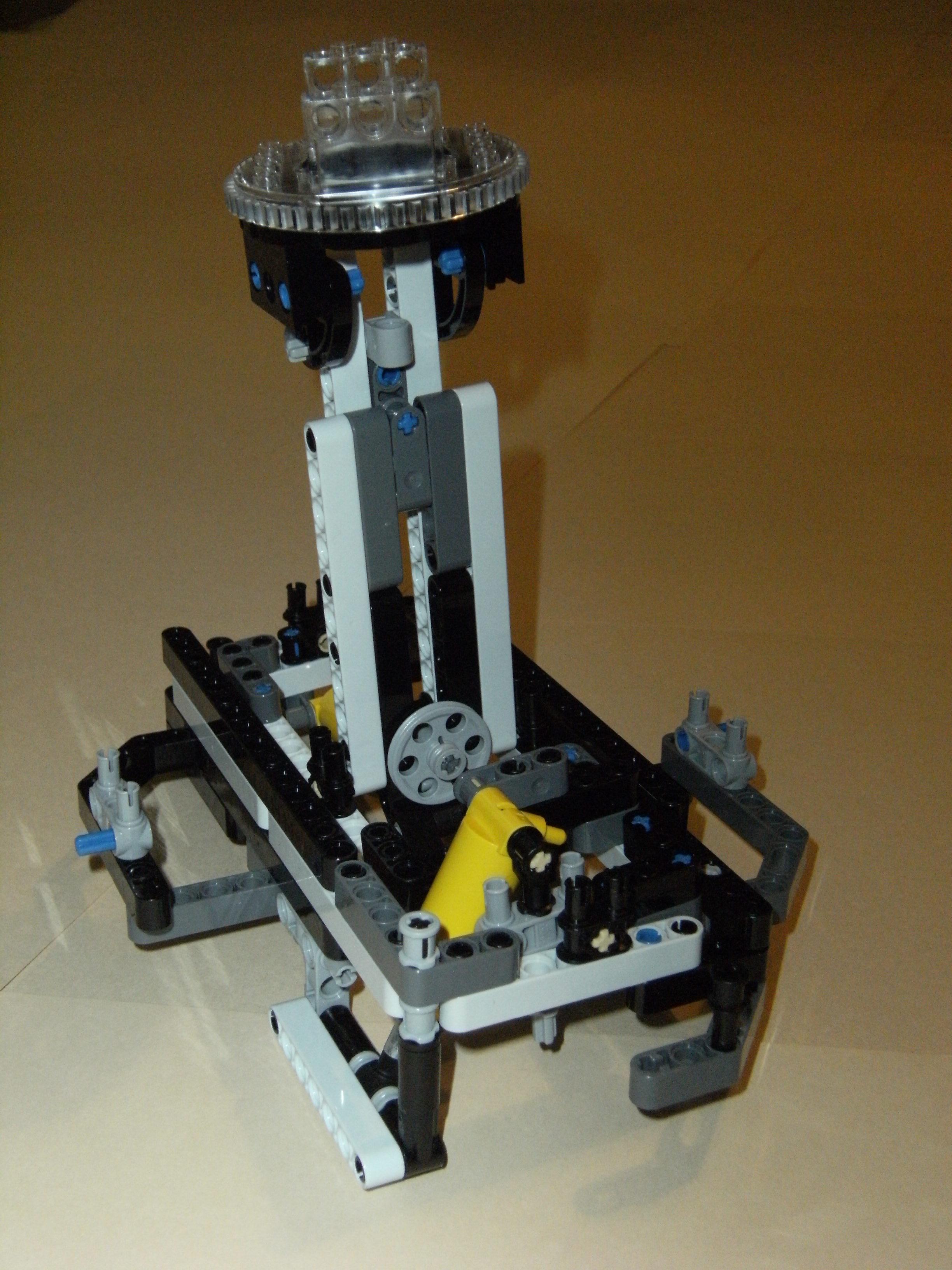
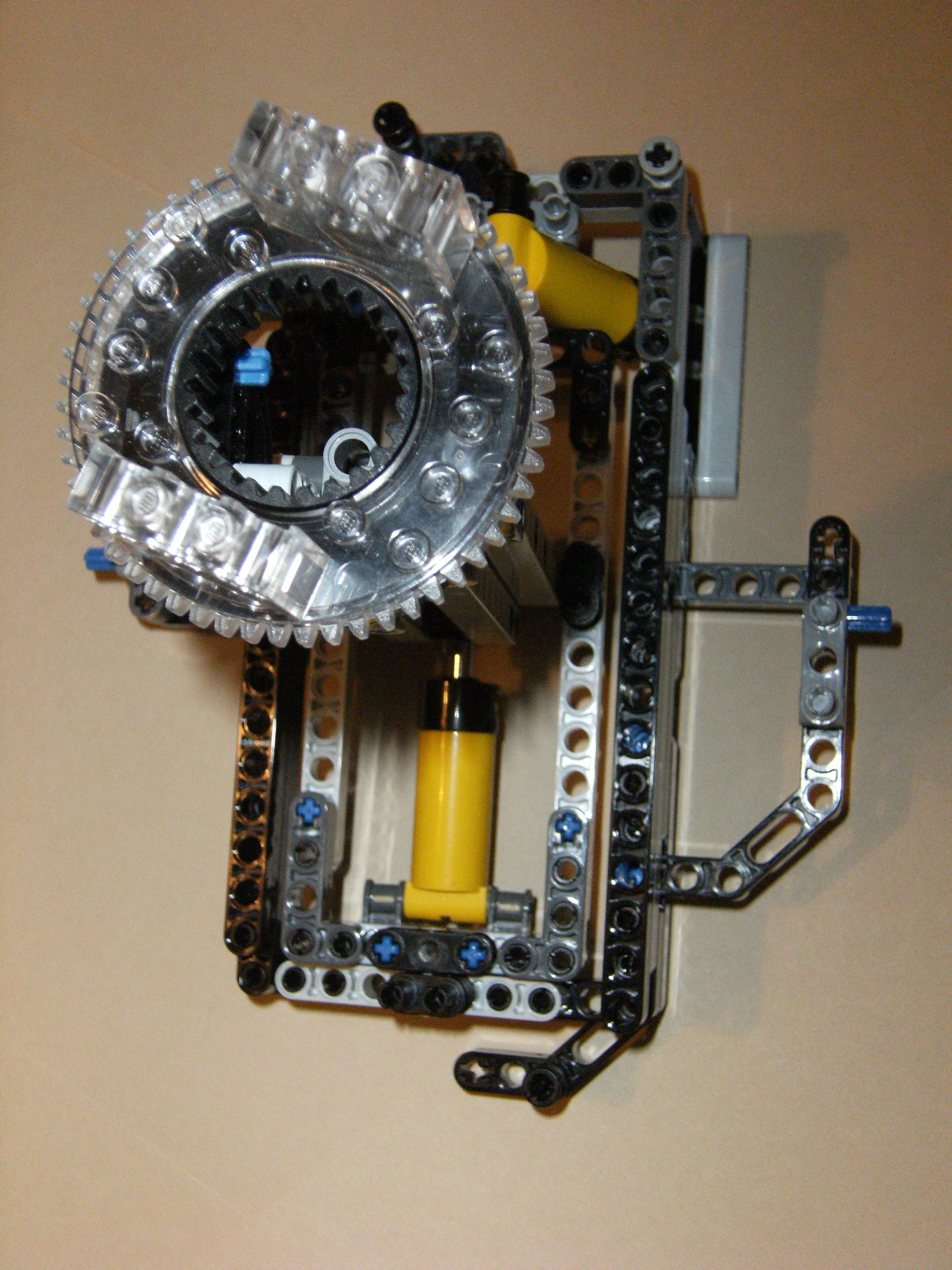
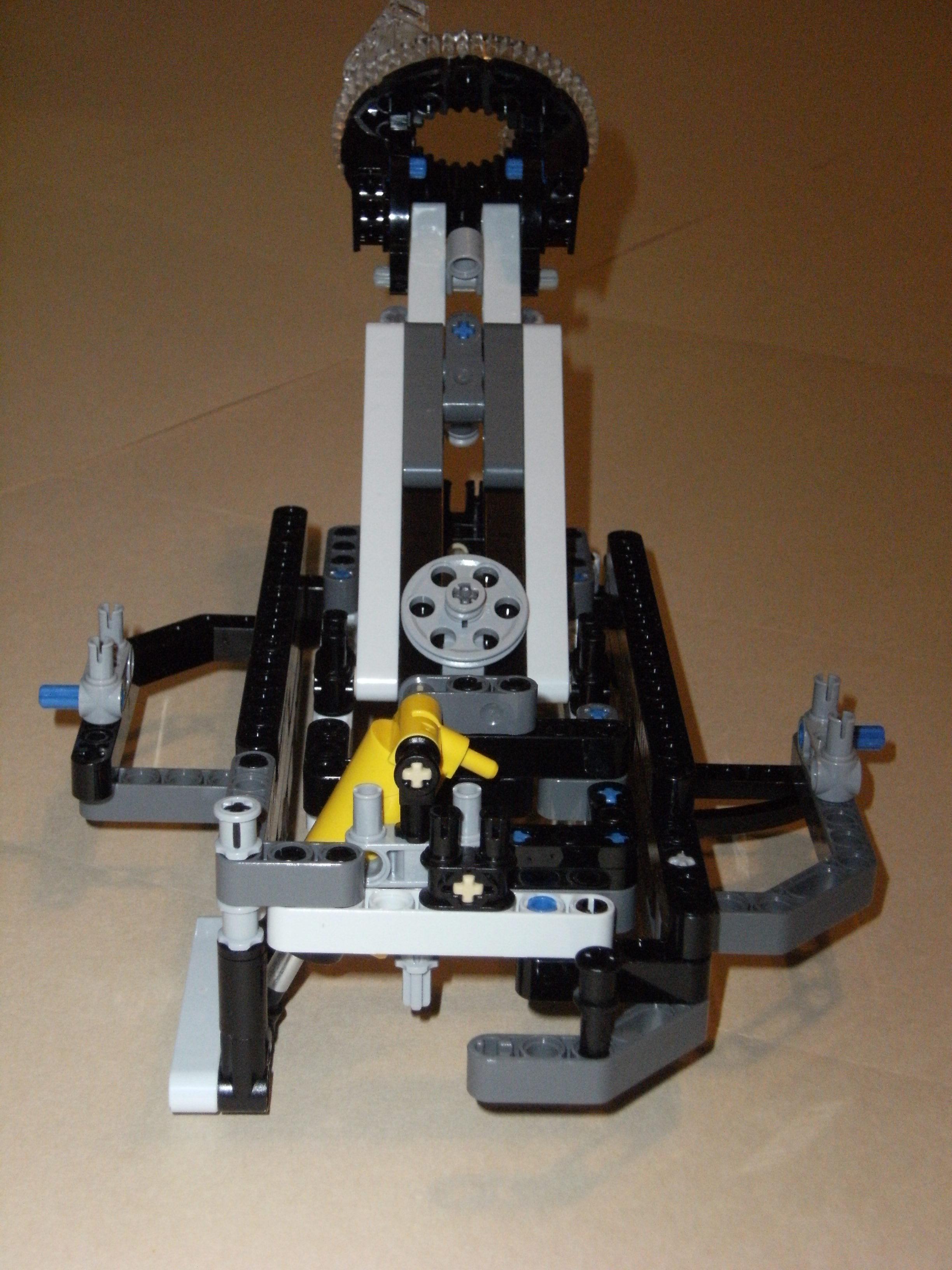
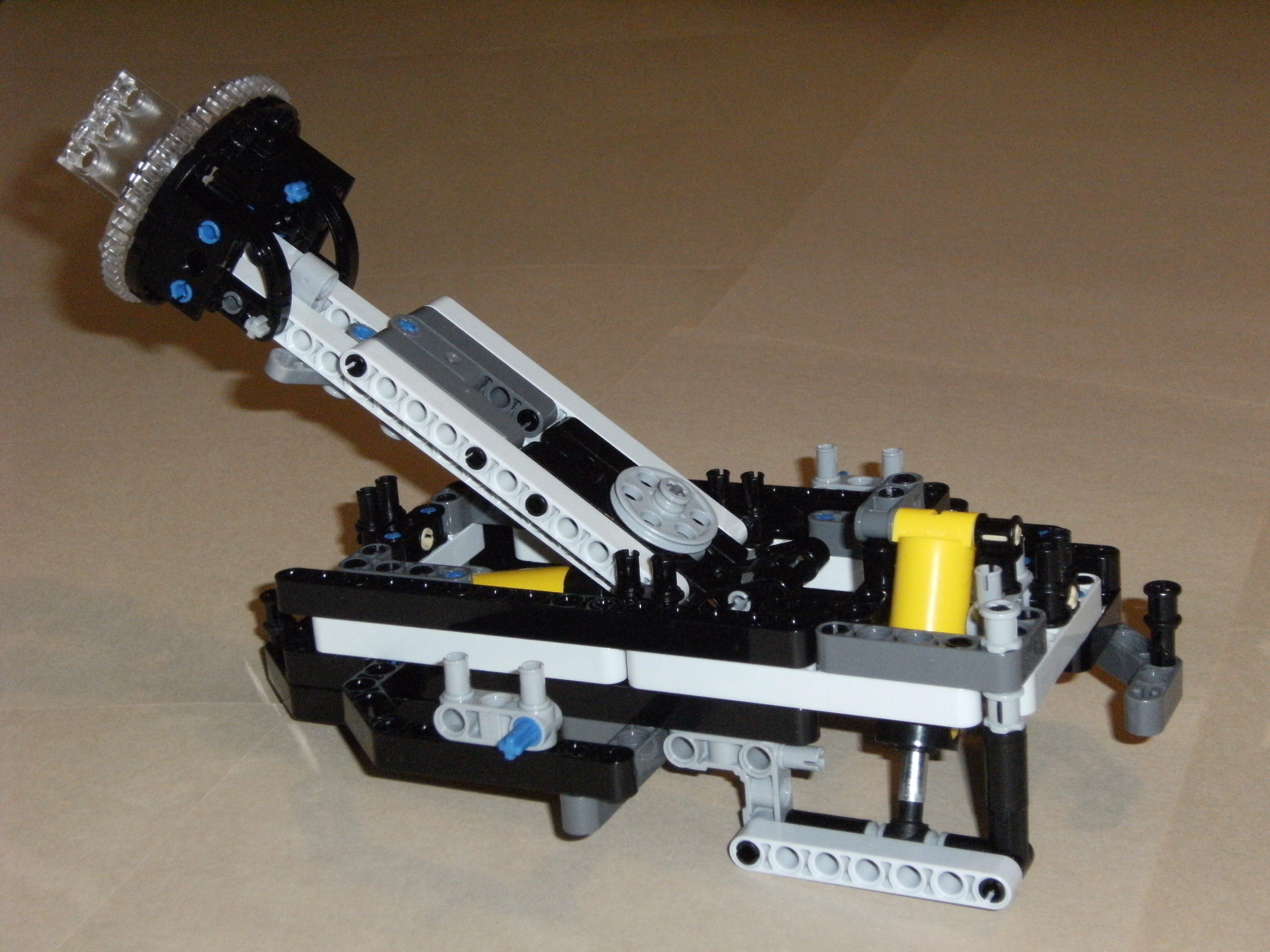
A Single Module |
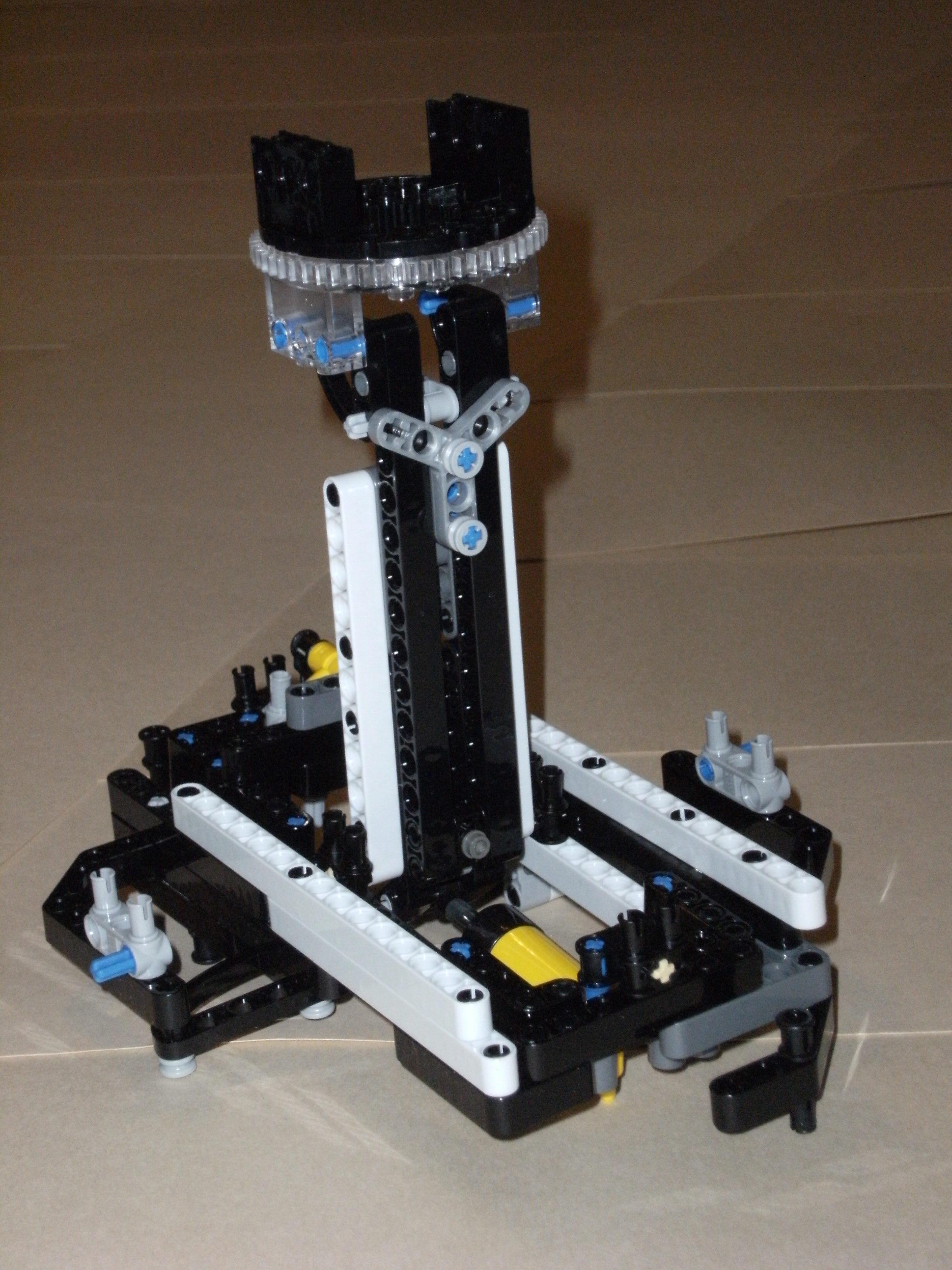
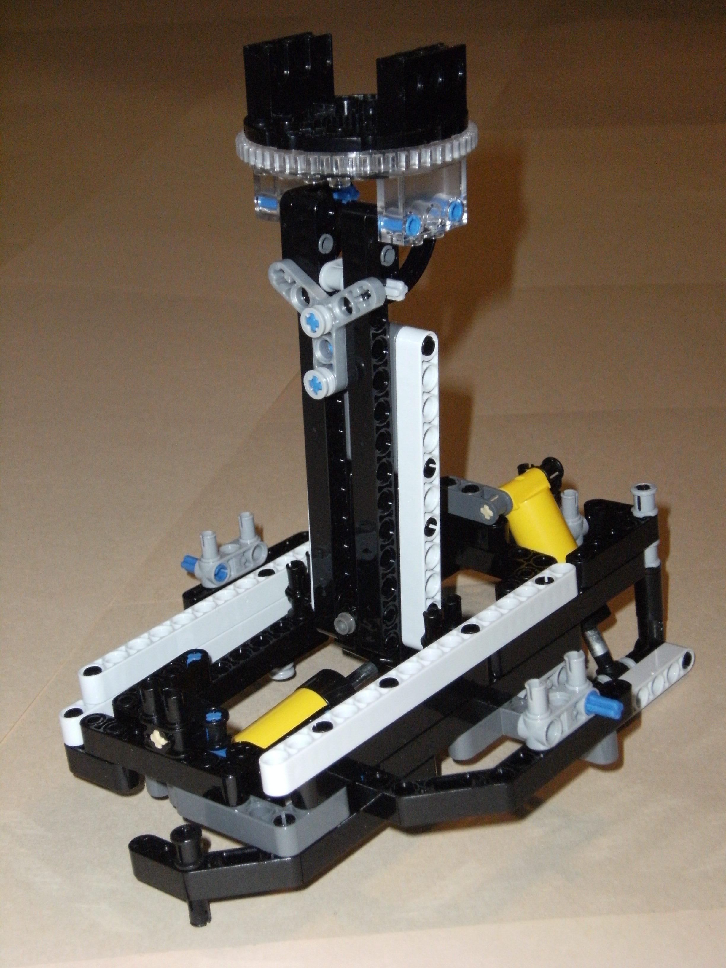
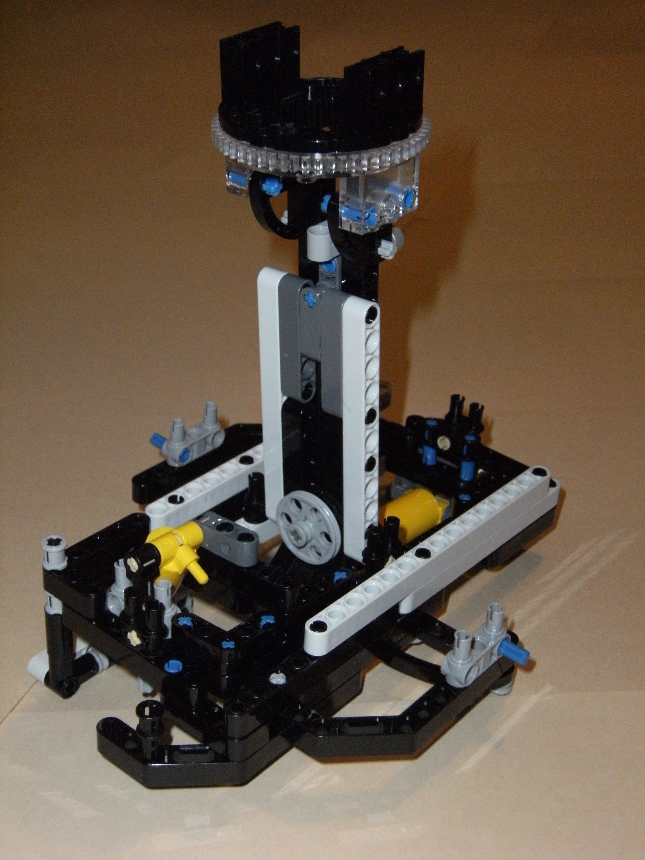
This video shows a Lego mock-up of a single module’s motion and movement capabilities:
|
|
|
[EMBED VIDEO HERE] Two Module |
This video of two Lego mock-ups of a module shows how they can be connected together:
|
|
|
[EMBED VIDEO HERE] Three Module |
This video has three Lego mock-ups of a module. Two of them are initially connected along their sides to each other. The video will show the third one being connected to each of the two that are connected together in such a way that they all share a common cube corner. | |
|
[EMBED VIDEO HERE] Mesh Connections |
This video consists of an example of a mesh of Lego mock-up modules. It shows how any module in the mesh can be disconnected at one point and reconnected at a different point that is available and within range. | |
|
[EMBED VIDEO HERE] Triple Parallel Mesh |
In this video, a mesh of Lego mock-up modules are connected together. They are connected in such a way that there are two sets of three modules that are connected together to share a common cube corner and the legs from each set connect the two sets together. It shows the motion and shaping capabilities of such a structure. | |
|
[EMBED VIDEO HERE] Genderless Connecting |
This video shows a new improved version of Lego mock-up modules. The connecting plates are now gender-independent, meaning any two modules can connect together via their connecting plates. This is illustrated in this video by showing 3 modules all able to connect to each other via their connecting plates. | |
|
[EMBED VIDEO HERE] Part 1 of 2 |
Self-Reconfiguring Technology: Universal Module-Cell Utility System – “a concept”
Part 1 of 2: Modules and Cells Section 1: Module Assembly Components |
|
|
[EMBED VIDEO HERE] Part 2 of 2 |
Self-Reconfiguring Technology: Universal Module-Cell Utility System – “a concept”
Part 2 of 2: Connecting and Disconnecting Section 6: Reconfiguring 3 “3-Dimensional” Cells into 4 “2-Dimensional” Cells |
| [EMBED VIDEO HERE]
Exploring Inductors |
In this video, inductance for transducer-to-transducer applications and the benefits to self-reconfigurable technology will be examined.
|
This terminology does not necessarily adhere to strict technical formality. It is only meant to serve as a reference guide for standardization of their use in the articles. Some of the older versions of articles do not yet comply with this standardization.
| TERM | WORKING DEFINITION OR EXPLANATION |
|---|---|
| cell | a collection of between two to six modules connected to each other via their rectangular bases a matrix element made up of at least three modules that are connected together in such a way as to share a common corner of a partial cube |
| full cell | a matrix element that consists of six modules and does not necessarily include a power cell; a cell that is not full consists of between 2 and 5 modules |
| complete cell | a matrix element made up of six modules (a full cell) and a power cell |
| pseudo-cell | a cell consisting of 2 modules |
| inverse cell | two modules connected to each other via their connecting plates |
| matrix | a group of modules or cells joined together primarily in a pattern |
| mesh | a cell matrix made up of a random arrangement of connections and positions |
| module | one of two fundamental elements that is a component in a matrix cell; an assembly of fabricated components; six modules make a full cell; this assembly consists of two ends connected together by a telescoping shaft, and contains moving parts, actuators, and electronics; one end is a connecting plate that can rotate about the axis of the telescoping shaft and can connect to the connecting plate of another module; the other (cell core fragment) end can connect directly to up to four other modules and a powercell (these four modules form a ring with the powercell in the center), to form the core of a cell, and a sixth module can connect to this core (on the “opposite side”) to form a full cell |
| powercell | one of two fundamental elements that is a component in a matrix cell; a cube-shaped housing for an electrical battery; the position of the conductors on the face of the cubes are arranged in a symmetric pattern that prevents reverse polarity from being possible |
| module component | one of the basic module assembly elements: the rectangular base, universal joint, telescoping shaft (leg), or connecting plate |
| module assembly | a single module, made up of the module components |
A number pattern convention can be used to identify modules when they are brought together to form a cell. In the Image below, Figure A shows a 3-dimensional cube with the faces that are showing numbered 1, 2, and 3 in a counter-clockwise direction about their common corner. Figure B shows the cube unfolded to indicate how all the faces of the cube are numbered in relation to each other. The numbering convention for determining which faces have values 4, 5, and 6 is to arrange them so that the sum of the values from each pair of opposite faces is equal to 7.
A cell module consists of several moving parts. There are 4 basic assemblies that make up a cell module, and each assembly consists of several components. The following is a list of the assemblies and the mechanical components of each assembly involved in the interaction between assemblies and modules (all assemblies consists of internal mechanical components that are not included here):
The following list describes all of the types of assembly movements:
The following list describes all of the types of inter-modular connections:
When two modules connect to, or just come in contact with, each other with the connecting plate surfaces, there are 3 ways this can happen. One way this can happen is if the surfaces only touch each other, but there is no interlocking bond; only pressure or stability are involved, and only pushing but not pulling can take place between the two modules. Another way this can happen is if there is a mechanical interlocking bond; this would be the prefereable means for long term or unpowered bonds. The last is if there is a powered electrical bond; if energy is removed, then the bond is broken; this would be the preferable means of bonding two modules in situations where connections have a very short duration and there is frequent connecting and disconnecting activity. A bond involving both mechanical and powered electrical means is possible and could be considered a fourth way, but in practice this would be extraneous or unnecessary (unless the interlocking mechanism is designed to be breakable by excessive tension and the powered electrical bond is necessary for providing more strengh).
There are 4 types of schematic symbols for depicting 2 modules in contact with each other. In the image below, Figure 2a shows 2 modules A and B connected to each other without reference to the type of bond; Figure 2b shows 2 modules A and B connected without either type of bond; Figure 2c shows 2 modules A and B connected with only a powered electrical bond; finally, Figure 2d shows 2 modules A and B connected with at least a mechanical bond (it either may or may not have a powered electrical bond).