Sensor-Based Distance Determination for Centers of Two Cells Chained Through a Third Cell

SENSOR-BASED DISTANCE DETERMINATION FOR CENTERS OF TWO CELLS CHAINED THROUGH A THIRD CELL

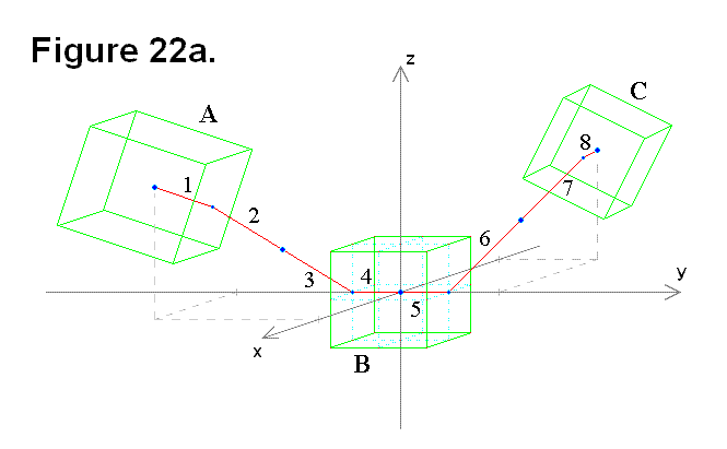
Certain lengths and angles can either be measured with sensors or are known constants that can be used to calculate the distance between the centers of two cells connected to a middle (third) cell such that they are chained in series. In order to determine the distance, each involved module within each cell would have to perform calculations on shared readings from both its own sensors and sensors on the other modules that are involved. In Figures 22a and 22b, 3 cells A, B, and C are drawn as three-dimensional green wire frames to represent the core of the cells (i.e., the cube-shaped region that doesn’t include the telescoping legs and connecting plates). The red numbered lines represent the measureable sections, they are either the distance from the center of the cell cube to the center of the face on the cube surface (all are equal and constant), or the length of the telescoping leg (each one is a variable value). There are two ways that 3 cells can be chained in series. One is shown in Figure 22a, where two cells (A & C) are connected to the middle cell (B) on opposite sides through it along the y-axis. In either case, the numbered red lines are:

  1. Cell cube center to center of face for cell A connected to 2
  2. Leg of cell A connected to 1 and 3
  3. Leg of cell B connected to 4 and 2
  4. Cell cube center to center of face for cell B connected to 3 and 5
  5. Cell cube center to center of face for cell B connected to 4 and 6
  6. Leg of cell B connected to 5 and 7
  7. Leg of cell C connected to 6 and 8
  8. Cell cube center to center of face for cell C connected to 7

The lengths of the “cell cube center to center of face” sections are all equal to each other in length L (i.e., L1 = L4 = L5 = L8 = L). For simplicity, all angle values written in formulas in this articleare limited to a single-cycle range of angle (0 ≤ angle < 2π).The other is shown in Figure 22b, where two cells (A & C) are connected to the middle cell (B) on adjacent sides through it along the positive y-axis, positive z-axis, and the x-y-z axes origin (where the 3 axes intersect).
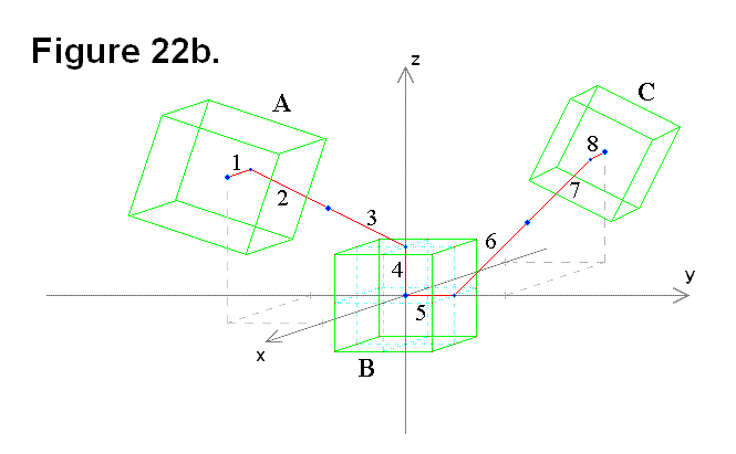
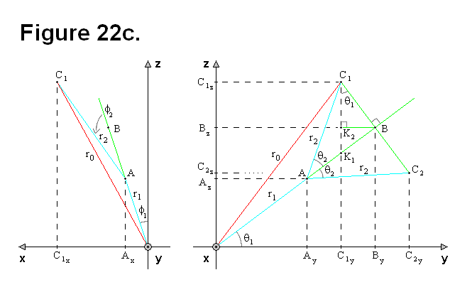
In Figure 22c, the focus is on only some of the red lines, sections 1, 2, and 3 (or alternatively, sections 6, 7, and 8), in Figures 22a and 22b. Vector r1 (line segment OA) corresponds to sections 2 and 3 in Figures 22a and 22b, and vector r2 (line segment AC) corresponds to section 1 in Figures 22a and 22b. Points C1 and C2 are actually two possible graphical representations of a single point C, which is the center of the cell cube. The actual sensors are the universal joint horizontal and vertical angles, the connecting plate rotation angle, and the telescoping leg length. Readings from these sensors can be used as input values in conversion formulas as part of the process to perform the distance calculations. Since θ corresponds to the pivot angle of the leg, and the leg pivots on the face of the cell cube, it is never going to be more than a magnitude of 90° (i.e., 0 ≤ |θ| ≤ π/2).
The following equations written in terms of r are 3-dimensional vector and magnitude formulas:

   (Formula #1)
    (Formula #2)

Although r1 = L, r1 will remain in the equations for clarity. From Figure 22c, the following equations can be derived:

  (Equation # 1)
  (Equation # 2)
  (Equation # 3)
  (Equation # 4)
  (Equation # 5)

If  1 = 0 and  2 = 0, the following equations can be derived and used.

  (Equation # 6)
  (Equation # 7)
  (Equation # 8)
  (Equation # 9)
  (Equation # 10)

The following two equations are independent of any angle value 2.

  (Equation # 11)
  (Equation # 12)

The length of r0 can be calculated without θ1, using only r1, r2, and θ2, but ry and rz cannot.

  (Equation # 13)

The following two equations apply only to point C1, not C2.

  (Equation # 14)
  (Equation # 15)

To make it easier to analyze the diagram in Figure 22c, some of the sections are redrawn in Figure 22d (Cartesian diagram on left side). The separate red-green-blue triangle in Figure 22d on the right side is a diagram of vector OB perpendicular to the plane of the diagram for arbitrary values of  2. 
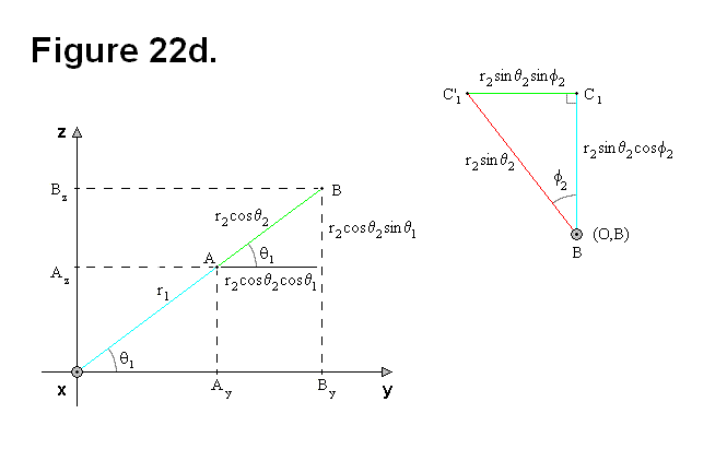
From Figure 22d, the following equations, which are independent of  2, can be derived:

  (Equation # 16)

If  1 = 0, the following equation can be derived.

  (Equation # 17)

For any angle value 2, in the y-z plane:

  (Equation # 18)
  (Equation # 19)
  (Equation # 20)

In red-blue-green triangle figure:

  (Equation # 21)
  (Equation # 22)

For  1 = 0 and arbitrary values of  2:

  (Equation # 23)

To generalize, the ρ-variables in the following equations are fixed to the formulas.

  (Equation # 24)
  (Equation # 25)
  (Equation # 26)

For any value of 1, Figure 20e shows the necessary components for continuing the geometric analysis to derive the necessary formulas. The Cartesian diagrams with the green wire frames are based on Figure 22c for representing arbitrary values of 1 and 2. The blue triangle involves lengths ρz and ρx, and introduces angle β to cover the situation of 1 = 0 and arbitrary values of 2. For 1 = 0, angle β is basically a function of 2 to allow for calculating α as a function of angles 1 and β; all that is necessary is to add the two angles.Based on Figure 22e, the following equations can be derived:
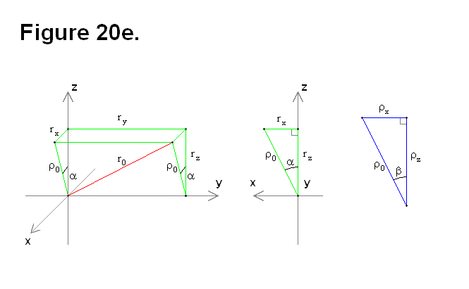
  (Equation # 27)
(Equation # 28)
  (Equation # 29)
  (Equation # 30)
  (Equation # 31)
  (Equation # 32)
  (Equation # 33)

Now from the previous equations, the following formulas can be derived:

  (Equation # 34)
  (Equation # 35)
  (Equation # 36)
  (Equation # 37)

To calculate the distance d from the origin O to the center of cell A (shown in Figure 22a), all that is necessary is to include section 4 in the equations:

  (Equation # 38)
  (Equation # 39)
  (Equation # 40)

The previous three equations are re-written to include both sections 1-4 and 5-8 in Figure 22a. The next three are for sections 1-4:

  (Equation # 41)
  (Equation # 42)
  (Equation # 43)

The next three equations are for sections 5-8:

  (Equation # 44)
  (Equation # 45)
  (Equation # 46)

The following equations result from adding the last six equations together, to get the formulas for the distance D from the center of cell A to the center of cell C in Figure 22a:

  (Equation # 47)
  (Equation # 48)
  (Equation # 49)

The following three equations represent sections 5-8 in Figure 22b:

  (Equation # 50)
  (Equation # 51)
  (Equation # 52)

Cell Structure Forming Pattern Possibilities

CELL STRUCTURE FORMING PATTERN POSSIBILITIES

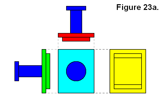
There are several ways a module can be attached to other modules to form a partial cell, full cell, or inverse cell. In Figure 23a, the different side views of a single module is shown in various colors. The leg and connecting plate assembly is a darker blue, and the rest of the module is a different color for the type of side. For the opposite sides that are symmetric, the longer (lengthwise) side are green, and the shorter (widthwise) sides are red. The surface on which the leg mounts is light blue, and the opposite side is yellow. In this diagram, the truncated pyramid-shaped surface shown in this article: Module Connection Arrangement Patterns of a Cell is omitted, but the yellow side corresponds to the side on which it is mounted.

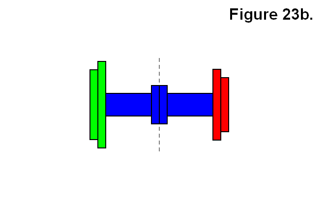
One type of connection of a module is to another single module via the connecting plates. This is shown in Figure 23b and is referred to as an “inverse cell.” The idea is that in the same way a mesh or matrix can be made of cells, and cells are made using modules, a mesh or matrix can also be made of inverse cells, and inverse cells can also be made using modules. In this figure, different colors do not necessarily signify different modules. Both the legs and the connecting plates of both modules are dark blue. On the left side of the line indicated by a vertical series of gray dashes is one module with a green lengthwise side shown, and on the right the other module with a red widthwise side shown. It is not necessary for the opposite types of side indicated by red or green to be aligned with each other from the two modules or to be aligned in general. It is only shown this way to make it easier to identify each module. The different resulting patterns will be categorized with abstract codes as connection types. A single module will be categorized simply as M. The resulting module structure in Figure 23b will be categorized as connection type T.

An expression describing the connection will also be given in the forms F → R or R ← F, meaning “F can form R,” where R is the resulting form and F is an abstract representation of “X + Y,” which means the joining of object X to object Y, and it is commutative (i.e., X + Y and Y + X are interchangeable). The objects X and Y each can be either a module M or a partially constructed cell R.

Expression: M + M → T

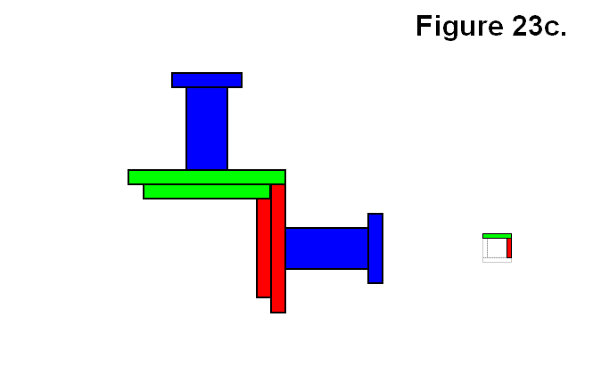
Another type of connection of a module M to another single module M is via the rectangular bases, which is to connect one along one of the green surfaces side (not shown) to the yellow widthwise side (not shown) of another in the type of orientation and alignment shown in Figure 23c. The smaller square to the right is an abstract icon representing the view angle of the figure with corresponding color pattern (shown for future reference). In this figure as well, different colors do not necessarily signify different modules. Both the legs and the connecting plates of both modules are dark blue. In this case it is necessary for the opposite types of side indicated by red or green to be aligned with each other from the two modules to be aligned. The different resulting patterns will be categorized with abstract codes as connection types. A single module will be categorized simply as M. The resulting module structure in Figure 23c will be categorized as connection type A. A formula describing the connection will also be given, for instance:

Expression: M + M → A

In the remaining part of this article the side views of the dark blue leg and connecting plate will be omitted from the diagrams and will only be limited to connections via the rectangular bases.

A single module can also be connected to a group made up of 2 to 5 modules connected together via their rectangular bases. Figure 23d shows one way of connecting a module M to each of a pair of modules A resulting in a partial cell in which all three modules share a common corner. The icon on the left is shown as a different angle than the figure image, and sometimes the view of the module in the back is obstructed by the one in front, so the gray circle with the smaller icons represent the side of the viewing direction of the figure (not present if viewing directions are the same) to reveal the presence of modules in the back on the icon. This resulting module structure will be categorized as connection type Bx.

Expression: A + M → Bx

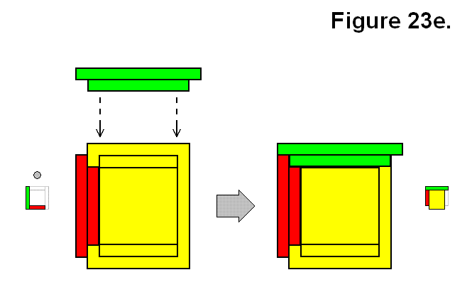
Figure 23e shows a reflective way a of connecting a module M to each of a pair of modules A resulting in a partial cell in which all three modules share a common corner, which is a mirror image of the version in Figure 23d. This resulting module structure will be categorized as connection type By.

Expression: A + M → By

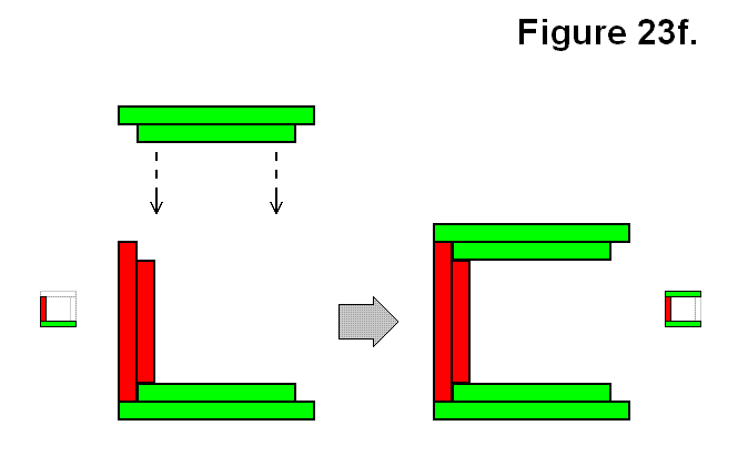
Instead of adding a single module M to a pair of modules resulting in a common corner, it can be added to one of the modules to be on the opposite side of the other module of an A structure. Figure 23f shows one version of this type of structure, categorized as connection type Ux.

Expression: A + M → Ux

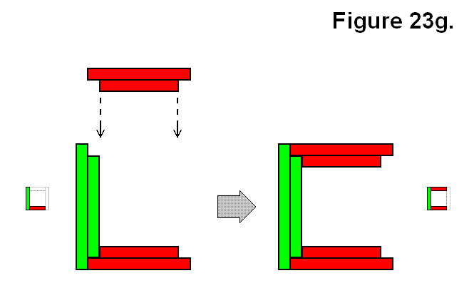
Figure 23g shows another version of the type of structure similar in arrangement pattern to the structure of Figure 23f using an M and A structure, categorized as connection type Uy. These two from Figures 23f and 23g are opposites to each other in that they can join together to form a full cell.

Expression: A + M → Uy

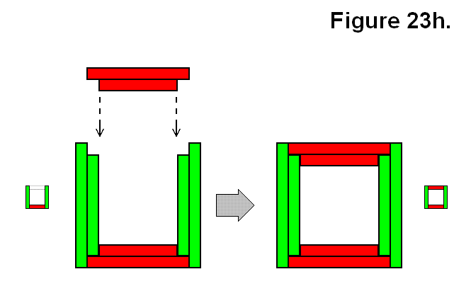
Another way in which a single module M can be connected to a group of multiple modules connected together via their rectangular bases is shown in Figure 23h, which is to connect it to a set of 3 modules in a Ux structure. This is one version that results in this pattern where the 4 modules joined together results in a 2D alternating cycled pattern, to be categorized as connection type O.

Expression: Ux + M → O

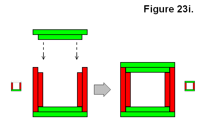
The other way to join a single module M to 3 other modules to result in connection type O is shown in Figure 23i, by using a Uystructure.

Expression: Uy + M → O

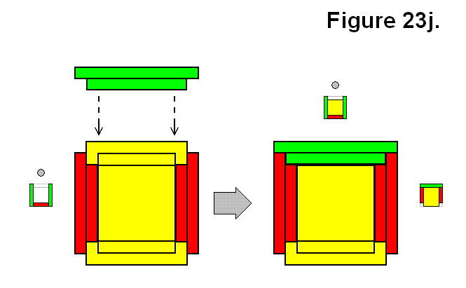
Another way to connect a module M to a set of 3 modules in a Ux structure is shown in Figure 23j. This is one version that results in a pattern where the 4 modules joined together do not result in the 2D alternating cycled patterns of Figures 23h and 23i, to be categorized as connection type G.

Expression: Ux + M → G

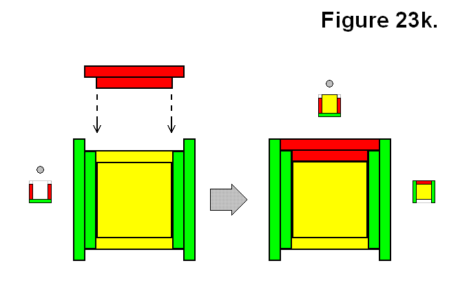
Figure 23k also shows another way to connect a module M to a set of 3 modules, which are in a Uy structure, resulting in a G structure.

Expression: Uy + M → G

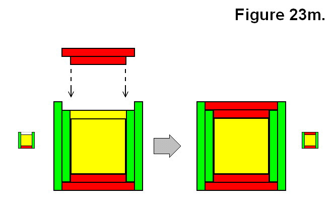
Another way in which a single module M can be connected to a group of multiple modules connected together via their rectangular bases is shown in Figure 23m, which is to connect it to a set of 4 modules in a G structure. This one is to be categorized as connection type Q.

Expression: G + M → Q

Figure 23n also shows another way to connect a module M to a set of 4 modules in a G structure which also results in a connection type Q.

Expression: G + M → Q

Figure 23o shows a way to connect a module M to a set of 4 modules in an O structure pattern for form a Q structure.

Expression: O + M → Q

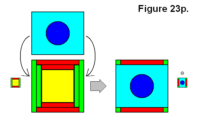
Figure 23p shows a full cell, categorized as connection type C, made by connecting a module M to a Q structure.

Expression: Q + M → C

Forming a structure is not limited to being possible by adding just a module M to another structure. Two structures A and A can be joined together to form a structure. A structure O made by joining two structures A and A is shown in Figure 23q.

Expression: A + A → O

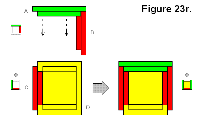
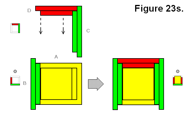
A structure G can be made by joining two structures A and A as shown in different perspectives in Figures 23r and 23s. Since it might not be simple to determine that different views are the same structure forming connection pattern, the modules are labeled A, B, C, and D to indicate which ones in Figure 23r can correspond to the ones in Figures 23s.

Expression: A + A → G


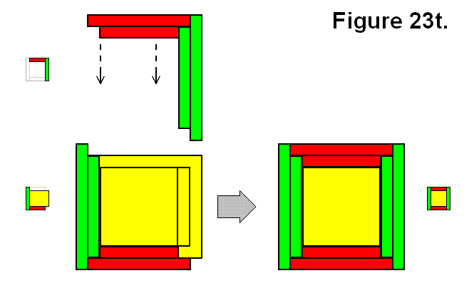
A structure Q can be made by joining two structures A and By as shown in Figure 23t.

Expression: A + By → Q

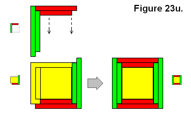
A structure Q can also be made by joining two structures A and Bx as shown in Figure 23u.

Expression: A + Bx → Q

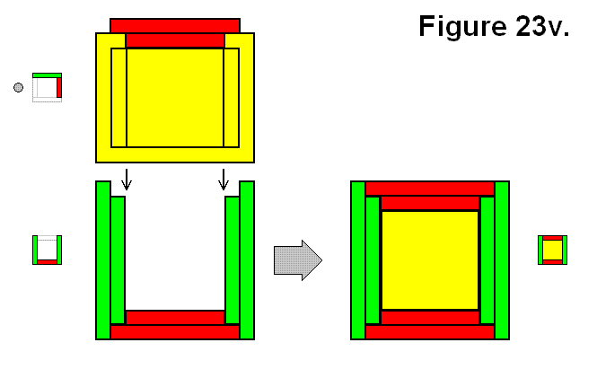
A full cell structure Q can be made by joining two structures A and Ux as shown in Figure 23v.

Expression: A + Ux → Q

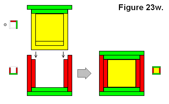
A full cell structure Q can also be made by joining two structures A and Uy as shown in Figure 23w.

Expression: A + Uy → Q

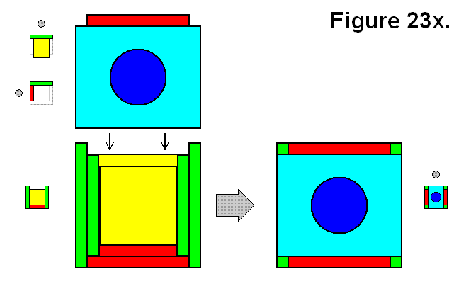
A full cell structure C can be made by joining two structures A and G as shown in Figure 23x.

Expression: A + G → C

A full cell structure C can also be made by joining two symmetrically opposite B structures Bx and By as shown in Figure 23y.

Expression: Bx + By → C

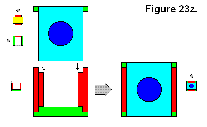
A full cell structure C can also be made by joining two symmetrically inverse U structures Ux and Uy as shown in Figure 23z.

Expression: Ux + Uy → C

The following table summarizes the expressions, and groups each connection F with matching results R or vice versa by separating each possible type of joining connection or result by a “|” symbol (meaning “or”), listed by number of modules in the resulting cell. If the subscript is omitted it means all versions are included.


Number of Modules Expression
2 M  + M   → A  | T
3 A  + M   → B  | U
4 O  | G   ← U + M  | A + A
5  Q   ← G + M  | O + M  | A + B  | A + U
6  C   ← Q + M  | A + G  | Bx + By  | Ux + Uy


The following table summarizes the distinct possible “|” separated R result patterns arranged in order of number of modules in each joining part.


Structure Connections Resulting Pattern Possibilities Notes
1: + 1 = 2 A  | T only one possible way to form each
+ 2 = 3 Bx  | By  | Ux  | Uy only one possible way to form each
+ 3 = 4 O  | G two symmetrically complementary possible ways to form each
+ 4 = 5 Q three possible ways to form, two are complementary to each other
+ 5 = 6 C only one possible way to form
2: + 2 = 4 O  | G only one possible way to form each
+ 3 = 5 Q four possible ways to form, 2 pairs of symmetrical compements
+ 4 = 6 C only one possible way to form
3: + 3 = 6 C two symmetrically complementary possible ways to form


Self Structuring and Computing System

SELF STRUCTURING AND COMPUTING SYSTEM

A modular self structuring and computing system includes a matrix formed of a plurality of modules. Each module comprises up to six connecting assemblies that are detach­ably coupled to one another through pin and hole type connections to form a housing for a power source. Each connecting assembly includes a pivotally mounted leg with a connecting plate attached thereto and a central connector. The power source located at the center of the module communicates with each of the central connectors. Various modules in a matrix can be directed to move or pivot their legs to move or change the overall structure of the matrix or to conduct a task, such as replacing the power source of a module.

View on USPTO

A Modular Self Structuring and Computing System

A MODULAR SELF STRUCTURING AND COMPUTING SYSTEM

A modular self-structuring computing system includes a matrix formed of a plurality of modules. Each module has a set of connecting legs, a set of connecting plates, an internal computer system and an internal power system. Preferably, a center housing is provided with six extending legs having connecting plates on the end of each leg. The housing, or core, supports the legs in a pivotal manner and includes compartments for energy cells and a computer processor. Groups of elements may be formed into a matrix type structure and by directing various modules to move or pivot their legs, the overall structure can move to change its shape and/or size.

View on USPTO

Electromagnetic Communication and Connection System

ELECTROMAGNETIC COMMUNICATION AND CONNECTION SYSTEM

Abstract: An electromagnetic communication and connection system for self structuring and computing modules includes one or more inductors located on a connecting plate of a first module for communicating signals to one or more inductors located on a connecting plate of a second module. A com­puter processor and algoritlnn are utilized to calculate the spatial relationship of the two modules, and to facilitate alignment of respective connecting plates to achieve an aligned mechanical contact between the respective connect­ing plates. Once connected, a permanent or semi-permanent physical connection is maintained between the connecting plates and the modules may communicate with one another.

View on USPTO

Self-Reconfiguring Modular Robotics – Wikipedia

SELF-RECONFIGURING MODULAR ROBOTICS – WIKIPEDIA

Modular self-reconfiguring robotic systems or self-reconfigurable modular robots are autonomous kinematic machines with variable morphology. Beyond conventional actuation, sensing and control typically found in fixed-morphology robots, self-reconfiguring robots are also able to deliberately change their own shape by rearranging the connectivity of their parts, in order to adapt to new circumstances, perform new tasks, or recover from damage…

Read Full Wiki Entry

Robotics: Exotic Robots: Modular and fractal Robots

ROBOTICS: EXOTIC ROBOTS: MODULAR AND FRACTAL ROBOTS

A robot is generally designed for one particular activity, or at best a few closely related activities. This of course isn’t the ideal situation as many jobs require a large number of very different activities. For example, building the walls of a house and installing plumbing and electricity require very different tools and techniques. In practice this means you’ll end up designing either several different robots or a very complicated one…

Read Full WikiBook Entry

Programmable matter – Wikipedia

PROGRAMMABLE MATTER – WIKIPEDIA

Programmable matter is matter which has the ability to change its physical properties (shape, density, moduli, conductivity, optical properties, etc.) in a programmable fashion, based upon user input or autonomous sensing. Programmable matter is thus linked to the concept of a material which inherently has the ability to perform information processing.

Read Full Wiki Entry

Molecubes For Everyone

MOLECUBES FOR EVERYONE

<div style=”float: right; margin-right: 22px;”>

</div>At the Creative Machines Lab we build robots that do what you’d least expect robots to do: Self replicate, self-reflect, ask questions, and even be creative. We develop machines that can design and make other machines – automatically. Our work is inspired from biology, as we seek new biological concepts for engineering and new engineering insights into biology…

Visit Creative Machines Lab Columbia University